101-1121 Rabbit Semiconductor, 101-1121 Datasheet - Page 39
101-1121
Manufacturer Part Number
101-1121
Description
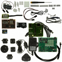
KIT CAMERA INTERFACE APPLICATION
Manufacturer
Rabbit Semiconductor
Series
RabbitCore 3000r
Specifications of 101-1121
Sensor Type
Motion, PIR (Pyroelectric Infrared)
Interface
10/100 BaseT Ethernet
Embedded
Yes, Other
Utilized Ic / Part
RCM3365
Interface Type
Ethernet
Lead Free Status / RoHS Status
Contains lead / RoHS non-compliant
Voltage - Supply
-
Sensitivity
-
Sensing Range
-
Lead Free Status / Rohs Status
Lead free / RoHS Compliant
Other names
316-1119


4.1.1 Memory I/O Interface
The Rabbit 3000 address lines (A0–A18) and all the data lines (D0–D7) are routed
internally to the onboard flash memory and SRAM chips. I/0 write (/IOWR) and I/0 read
(/IORD) are available for interfacing to external devices—pay attention to the loading on
these two signals if you use them since these signals are also used by the RCM3365/
RCM3375.
Parallel Port A can also be used as an external I/O data bus to isolate external I/O from the
main data bus. Parallel Port B pins PB2–PB7 can also be used as an auxiliary address bus.
When using the external I/O bus for a digital output or the LCD/keypad module on the
Prototyping Board, or for any other reason, you must add the following line at the begin-
ning of your program.
4.1.2 Other Inputs and Outputs
The status, /RESET_IN, SMODE0, and SMODE1 I/O are normally associated with the
programming port. Since the status pin is not used by the system once a program has been
downloaded and is running, the status pin can then be used as a general-purpose CMOS
output. The programming port is described in more detail in Section 4.2.3.
/RES is an output from the reset circuitry that can be used to reset external peripheral
devices.
4.1.3 LEDs
The RCM3365/RCM3375 has five status LEDs located beside the RJ-45 Ethernet jack:
ACT
The yellow
The green
working network.
The green
nected to a 100Base-T Ethernet connection.
The
storage device.
The red
the Rabbit 3000’s Parallel Port D. The sample program FLASHLED.C provided in the
Dynamic C
programmable LED.
User’s Manual
FM
,
LINK
#define PORTA_AUX_IO
LED at DS3 blinks when data are being written to or read from the flash mass-
USR
LINK
SPEED
,
ACT
SAMPLES\RCM3360
SPEED
LED at DS3 is a user-programmable LED, which is controlled by PD0 on
LED at DS2 indicates that the RCM3365/RCM3375 is connected to a
LED at DS1 indicates network activity.
LED at DS4 is on to indicate when the RCM3365/RCM3375 is con-
,
FM
, and
USR
folder shows how to set up and use this user-
// required to enable external I/O bus
.
33
Related parts for 101-1121
Image
Part Number
Description
Manufacturer
Datasheet
Request
R

Part Number:
Description:
KIT DEV FOR BL2500 COYOTE
Manufacturer:
Rabbit Semiconductor
Datasheet:

Part Number:
Description:
KIT APPLICATION SIMPLE SENSOR
Manufacturer:
Rabbit Semiconductor
Datasheet:


Part Number:
Description:
KIT APPLICATION LCD COLOR INT'L
Manufacturer:
Rabbit Semiconductor

Part Number:
Description:
IC CPU RABBIT2000 30MHZ 100PQFP
Manufacturer:
Rabbit Semiconductor
Datasheet:

Part Number:
Description:
IC CPU RABBIT4000 128-LQFP
Manufacturer:
Rabbit Semiconductor
Datasheet:
Part Number:
Description:
IC MPU RABIT3000A 55.5MHZ128LQFP
Manufacturer:
Rabbit Semiconductor
Datasheet:

Part Number:
Description:
MODULE RABBITCORE RCM4010
Manufacturer:
Rabbit Semiconductor
Datasheet:

Part Number:
Description:
RCM4110 RABBITCORE
Manufacturer:
Rabbit Semiconductor
Datasheet:

Part Number:
Description:
MODULE RABBITCORE RCM2000
Manufacturer:
Rabbit Semiconductor
Datasheet:

Part Number:
Description:
MODULE RABBITCORE RCM3000
Manufacturer:
Rabbit Semiconductor
Datasheet:

Part Number:
Description:
MCU RCM4000 RABBITCORE
Manufacturer:
Rabbit Semiconductor
Datasheet:

Part Number:
Description:
MODULE RCM4210 RABBITCORE
Manufacturer:
Rabbit Semiconductor
Datasheet:

Part Number:
Description:
MODULE RCM4200 RABBITCORE
Manufacturer:
Rabbit Semiconductor
Datasheet:

Part Number:
Description:
MODULE RABBITCORE RCM2020
Manufacturer:
Rabbit Semiconductor
Datasheet: