101-1121 Rabbit Semiconductor, 101-1121 Datasheet - Page 30
101-1121
Manufacturer Part Number
101-1121
Description
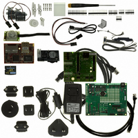
KIT CAMERA INTERFACE APPLICATION
Manufacturer
Rabbit Semiconductor
Series
RabbitCore 3000r
Specifications of 101-1121
Sensor Type
Motion, PIR (Pyroelectric Infrared)
Interface
10/100 BaseT Ethernet
Embedded
Yes, Other
Utilized Ic / Part
RCM3365
Interface Type
Ethernet
Lead Free Status / RoHS Status
Contains lead / RoHS non-compliant
Voltage - Supply
-
Sensitivity
-
Sensing Range
-
Lead Free Status / Rohs Status
Lead free / RoHS Compliant
Other names
316-1119


3.2.3 Serial Communication
The following sample programs can be found in the
•
•
•
•
24
FLOWCONTROL.C
Serial Port F for CTS/RTS with serial data coming from TxE (Serial Port E) at 115,200
bps. One character at a time is received and is displayed in the
To set up the Prototyping Board, you will need to tie
TxE and RxE together on the RS-232 header at J14,
and you will also tie TxF and RxF together as shown in
the diagram.
A repeating triangular pattern should print out in the
STDIO
demonstrate the effect of hardware flow control.
PARITY.C
byte values 0–127 from Serial Port E to Serial Port F. The program will switch between
generating parity or not on Serial Port E. Serial Port F will always be checking parity,
so parity errors should occur during every other sequence.
To set up the Prototyping Board, you will need to tie
TxE and RxF together on the RS-232 header at J14 as
shown in the diagram.
The Dynamic C
sequence.
SIMPLE3WIRE.C
Lower case characters are sent by TxE, and are received by RxF. The characters are
converted to upper case and are sent out by TxF, are received by RxE, and are displayed
in the Dynamic C
To set up the Prototyping Board, you will need to tie
TxE and RxF together on the RS-232 header at J14, and
you will also tie RxE and TxF together as shown in the
diagram.
SIMPLE5WIRE.C
by providing flow control (RTS/CTS) on Serial Port F and data flow on Serial Port E.
To set up the Prototyping Board, you will need to tie
TxE and RxE together on the RS-232 header at J14,
and you will also tie TxF and RxF together as shown in
the diagram.
Once you have compiled and run this program, you can
test flow control by disconnecting TxF from RxF while the program is running. Char-
acters will no longer appear in the
connected back to RxF. (Do not disconnect the data path between TxE and RxE.)
window. The program periodically switches RTS (TxF) flow control on or off to
—This program demonstrates the use of parity modes by repeatedly sending
STDIO
—This program demonstrates hardware flow control by configuring
—This program demonstrates basic RS-232 serial communication.
—This program demonstrates 5-wire RS-232 serial communication
STDIO
window will display the error
window.
STDIO
window, and will display again once TxF is
SAMPLES\RCM3360\SERIAL
RabbitCore RCM3365/RCM3375
STDIO
window.
folder.
Related parts for 101-1121
Image
Part Number
Description
Manufacturer
Datasheet
Request
R

Part Number:
Description:
KIT DEV FOR BL2500 COYOTE
Manufacturer:
Rabbit Semiconductor
Datasheet:

Part Number:
Description:
KIT APPLICATION SIMPLE SENSOR
Manufacturer:
Rabbit Semiconductor
Datasheet:


Part Number:
Description:
KIT APPLICATION LCD COLOR INT'L
Manufacturer:
Rabbit Semiconductor

Part Number:
Description:
IC CPU RABBIT2000 30MHZ 100PQFP
Manufacturer:
Rabbit Semiconductor
Datasheet:

Part Number:
Description:
IC CPU RABBIT4000 128-LQFP
Manufacturer:
Rabbit Semiconductor
Datasheet:
Part Number:
Description:
IC MPU RABIT3000A 55.5MHZ128LQFP
Manufacturer:
Rabbit Semiconductor
Datasheet:

Part Number:
Description:
MODULE RABBITCORE RCM4010
Manufacturer:
Rabbit Semiconductor
Datasheet:

Part Number:
Description:
RCM4110 RABBITCORE
Manufacturer:
Rabbit Semiconductor
Datasheet:

Part Number:
Description:
MODULE RABBITCORE RCM2000
Manufacturer:
Rabbit Semiconductor
Datasheet:

Part Number:
Description:
MODULE RABBITCORE RCM3000
Manufacturer:
Rabbit Semiconductor
Datasheet:

Part Number:
Description:
MCU RCM4000 RABBITCORE
Manufacturer:
Rabbit Semiconductor
Datasheet:

Part Number:
Description:
MODULE RCM4210 RABBITCORE
Manufacturer:
Rabbit Semiconductor
Datasheet:

Part Number:
Description:
MODULE RCM4200 RABBITCORE
Manufacturer:
Rabbit Semiconductor
Datasheet:

Part Number:
Description:
MODULE RABBITCORE RCM2020
Manufacturer:
Rabbit Semiconductor
Datasheet: