MT18HVF6472Y-53EB1 Micron Technology Inc, MT18HVF6472Y-53EB1 Datasheet - Page 8
MT18HVF6472Y-53EB1
Manufacturer Part Number
MT18HVF6472Y-53EB1
Description
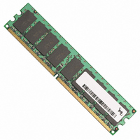
MODULE DDR2 512MB 240-DIMM VLP
Manufacturer
Micron Technology Inc
Datasheet
1.MT18HVF12872Y-53EB1.pdf
(15 pages)
Specifications of MT18HVF6472Y-53EB1
Memory Type
DDR2 SDRAM
Memory Size
512MB
Speed
533MT/s
Package / Case
240-DIMM
Lead Free Status / RoHS Status
Lead free / RoHS Compliant


Electrical Specifications
Table 6:
Capacitance
Table 7:
PDF: 09005aef82255aba/Source: 09005aef82255a83
HVF18C64_128_256x72G.fm - Rev. B 5/06 EN
Parameter
Parameter
V
V
V
Voltage on any pin relative to V
Storage temperature (2X refresh at 95°C)
DDR2 SDRAM device operating temperature
Input leakage current; Any input 0V ≤ V
V
under test = 0V
Output leakage current; 0V ≤ V
and ODT are disabled
V
Input high (logic 1) voltage
Input low (logic 0) voltage
Input high (logic 1) voltage (-667 speed grade)
Input low(logic 0) voltage (-667 speed grade)
Input leakage current; any input 0V ≤ V
not under test = 0V
Output leakage current; 0V ≤ V
disabled
Input/output capacitance
DD
DD
DD
REF
REF
Q supply voltage relative to V
L supply voltage relative to Vss
supply voltage relative to V
input 0V ≤ V
leakage current; V
Absolute Maximum DC Ratings
DRAM Interface for DRAM I/O
DRAM (at each individual device pin)
IN
≤ 0.95V; all other pins not
REF
= valid V
Stresses greater than those listed in Table 6 may cause permanent damage to the device.
This is a stress rating only, and functional operation of the device at these or any other
conditions above those indicated in the operational sections of this specification is not
implied. Exposure to absolute maximum rating conditions for extended periods may
affect reliability.
At DDR2 data rates, Micron encourages designers to simulate the performance of the
module to achieve optimum values. When inductance and delay parameters associated
with trace lengths are used in simulations, they are significantly more accurate and real-
istic than a gross estimation of module capacitance. Simulations can then render a
considerably more accurate result. JEDEC modules are now designed by using simula-
tions to close timing budgets.
OUT
OUT
SS
SS
SS
≤ V
REF
≤ V
DD
DD
level
IN
IN
Q; DQs
Q; DQ and ODT
≤ V
≤ V
DD
DD
; all other pins
;
RAS#, CAS#, WE# S#,
Command/address,
CKE, CK, CK#, DM
DQ, DQS, DQS#
1GB (x72, ECC, SR) 240-Pin DDR2 VLP RDIMM
8
Symbol
V
V
V
V
IH
IH
IL
IL
Ioz
C
(
(
Ii
(
(
IO
DC
AC
DC
AC
Micron Technology, Inc., reserves the right to change products or specifications without notice.
)
)
)
)
V
Symbol
IN
V
V
IV
V
V
T
V
T
DD
, V
Ioz
DD
CASE
REF
REF
DD
STG
I
REF
I
OUT
Q
L
(
(
–300
Min
DC
DC
–10
–10
5.5
–
) + 125
) + 200
Electrical Specifications
Min
–1.0
–0.5
–0.5
–0.5
–55
–10
–10
–46
0
©2003 Micron Technology, Inc. All rights reserved.
V
V
V
REF
REF
DD
(
(
Max
10.5
Q + 300
DC
DC
10
10
–
Max
) - 125
) - 200
100
2.3
2.3
2.3
2.3
95
10
10
46
Units
Units
µA
µA
µA
°C
°C
mV
mV
mV
mV
uA
uA
V
V
V
V
pF
Related parts for MT18HVF6472Y-53EB1
Image
Part Number
Description
Manufacturer
Datasheet
Request
R

Part Number:
Description:
IC SDRAM 64MBIT 133MHZ 54TSOP
Manufacturer:
Micron Technology Inc
Datasheet:

Part Number:
Description:
IC SDRAM 64MBIT 5.5NS 86TSOP
Manufacturer:
Micron Technology Inc
Datasheet:
Part Number:
Description:
IC SDRAM 64MBIT 200MHZ 86TSOP
Manufacturer:
Micron Technology Inc
Datasheet:
Part Number:
Description:
IC SDRAM 64MBIT 133MHZ 54TSOP
Manufacturer:
Micron Technology Inc
Datasheet:
Part Number:
Description:
IC SDRAM 128MBIT 133MHZ 54TSOP
Manufacturer:
Micron Technology Inc
Datasheet:

Part Number:
Description:
IC SDRAM 256MBIT 133MHZ 90VFBGA
Manufacturer:
Micron Technology Inc
Datasheet:
Part Number:
Description:
IC SDRAM 128MBIT 133MHZ 54TSOP
Manufacturer:
Micron Technology Inc
Datasheet:
Part Number:
Description:
IC SDRAM 256MBIT 133MHZ 54TSOP
Manufacturer:
Micron Technology Inc
Datasheet:

Part Number:
Description:
IC DDR SDRAM 512MBIT 6NS 66TSOP
Manufacturer:
Micron Technology Inc
Datasheet:
Part Number:
Description:
IC SDRAM 128MBIT 167MHZ 86TSOP
Manufacturer:
Micron Technology Inc
Datasheet:
Part Number:
Description:
IC SDRAM 128MBIT 143MHZ 86TSOP
Manufacturer:
Micron Technology Inc
Datasheet:

Part Number:
Description:
SDRAM 256M-BIT 1.8V 54-PIN VFBGA
Manufacturer:
Micron Technology Inc
Datasheet:
Part Number:
Description:
IC SDRAM 128MBIT 143MHZ 86TSOP
Manufacturer:
Micron Technology Inc
Datasheet:

Part Number:
Description:
IC SDRAM 128MBIT 125MHZ 54VFBGA
Manufacturer:
Micron Technology Inc
Datasheet:
Part Number:
Description:
IC SDRAM 128MBIT 125MHZ 54VFBGA
Manufacturer:
Micron Technology Inc
Datasheet: