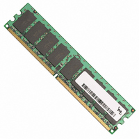
MT18HVF6472Y-53EB1 Micron Technology Inc, MT18HVF6472Y-53EB1 Datasheet - Page 7

MT18HVF6472Y-53EB1
Manufacturer Part Number
MT18HVF6472Y-53EB1
Description
MODULE DDR2 512MB 240-DIMM VLP
Manufacturer
Micron Technology Inc
Datasheet
1.MT18HVF12872Y-53EB1.pdf
(15 pages)
Specifications of MT18HVF6472Y-53EB1
Memory Type
DDR2 SDRAM
Memory Size
512MB
Speed
533MT/s
Package / Case
240-DIMM
Lead Free Status / RoHS Status
Lead free / RoHS Compliant
General Description
PLL and Register Operation
Serial Presence-Detect Operation
PDF: 09005aef82255aba/Source: 09005aef82255a83
HVF18C64_128_256x72G.fm - Rev. B 5/06 EN
Refer to the DDR2 component data sheets for complete functionality. For the 1GB
RDIMM device, refer to the 512Mb (128 Meg x 4) component data sheet.
DDR2 SDRAM modules are high-speed, CMOS, dynamic random-access 1GB memory
modules organized in x72 configuration. DRAM specifications require the refresh rate to
double when T
refresh option.
DDR2 SDRAM modules use double data rate architecture to achieve high-speed opera-
tion. The double data rate architecture is essentially a 4n-prefetch architecture with an
interface designed to transfer two data words per clock cycle at the I/O pins. A single
read or write access for the DDR2 SDRAM module effectively consists of a single 4n-bit-
wide, one-clock-cycle data transfer at the internal DRAM core and four corresponding
n-bit-wide, one-half-clock-cycle data transfers at the I/O pins.
A bidirectional data strobe (DQS, DQS#) is transmitted externally, along with data, for
use in data capture at the receiver. DQS is a strobe transmitted by the DDR2 SDRAM
device during READs and by the memory controller during WRITEs. DQS is edge-
aligned with data for READs and center-aligned with data for WRITEs.
DDR2 SDRAM modules operate from a differential clock (CK and CK#); the crossing of
CK going HIGH and CK# going LOW will be referred to as the positive edge of CK. Input
data is registered on both edges of DQS, and output data is referenced to both edges of
DQS, as well as to both edges of CK.
DDR2 SDRAM modules operate in registered mode, where the command/address input
signals are latched in the registers on the rising clock edge and sent to the DDR2 SDRAM
devices on the following rising clock edge (data access is delayed by one clock cycle). A
phase-lock loop (PLL) on the module receives and redrives the differential clock signals
(CK, CK#) to the DDR2 SDRAM devices. The registers and PLL minimize system and
clock loading. PLL clock timing is defined by JEDEC specifications and ensured by use of
the JEDEC clock reference board. Registered mode will add one clock cycle to CL.
DDR2 SDRAM modules incorporate serial presence-detect (SPD). The SPD function is
implemented using a 2,048-bit EEPROM. This nonvolatile storage device contains 256
bytes. The first 128 bytes can be programmed by Micron to identify the module type and
various SDRAM organizations and timing parameters. The remaining 128 bytes of
storage are available for use by the customer. System READ/WRITE operations between
the master (system logic) and the slave EEPROM device occur via a standard I
using the DIMM’s SCL (clock) and SDA (data) signals, together with SA (2:0), which
provide eight unique DIMM/EEPROM addresses. Write protect (WP) is tied to ground on
the module, permanently disabling hardware write protect.
CASE
exceeds 85°C. This also includes the use of the high-temperature
1GB (x72, ECC, SR) 240-Pin DDR2 VLP RDIMM
7
Micron Technology, Inc., reserves the right to change products or specifications without notice.
General Description
©2003 Micron Technology, Inc. All rights reserved.
2
C bus


