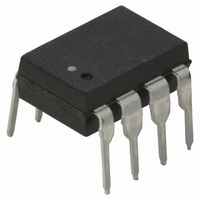
HCPL-7720-000E Avago Technologies US Inc., HCPL-7720-000E Datasheet - Page 15

HCPL-7720-000E
Manufacturer Part Number
HCPL-7720-000E
Description
OPTOCOUPLER CMOS 25MBD 8-DIP
Manufacturer
Avago Technologies US Inc.
Datasheet
1.HCPL-0720-000E.pdf
(19 pages)
Specifications of HCPL-7720-000E
Package / Case
8-DIP (0.300", 7.62mm)
Voltage - Isolation
3750Vrms
Number Of Channels
1, Unidirectional
Current - Output / Channel
10mA
Data Rate
25MBd
Propagation Delay High - Low @ If
20ns
Input Type
Logic
Output Type
Push-Pull, Totem-Pole
Mounting Type
Through Hole
Isolation Voltage
3750 Vrms
Maximum Continuous Output Current
10 mA
Maximum Fall Time
0.008 us
Maximum Forward Diode Current
10 mA
Output Device
Logic Gate Photo IC
Configuration
1 Channel
Maximum Baud Rate
25 MBd
Maximum Power Dissipation
150 mW
Maximum Operating Temperature
+ 85 C
Minimum Operating Temperature
- 40 C
No. Of Channels
1
Optocoupler Output Type
Gate Drive
Input Current
10µA
Output Voltage
5V
Opto Case Style
DIP
No. Of Pins
8
Common Mode Ratio
10000
Rohs Compliant
Yes
Lead Free Status / RoHS Status
Lead free / RoHS Compliant
Lead Free Status / RoHS Status
Lead free / RoHS Compliant, Lead free / RoHS Compliant
Other names
516-1689-5
Available stocks
Company
Part Number
Manufacturer
Quantity
Price
Company:
Part Number:
HCPL-7720-000E
Manufacturer:
AVAGO
Quantity:
5 000
Part Number:
HCPL-7720-000E
Manufacturer:
AVAGO/安华高
Quantity:
20 000
Figure 17. Recommended CC-Link application circuit.
Implementing CC-Link with the HCPL-772X/072X
CC-Link (Control and Communication Link) is developed
to merge control and information in the low-level net-
work (field network) by PCs, thereby making the mul-
tivendor environment a reality. It has data control and
message-exchange function, as well as bit control func-
tion, and operates at the speed up to 10 Mbps.
15
SLD
DA
DB
DG
FG
FIL
SN75ALS181NS
V
V
A
B
Y
Z
CC
CC
GND
GND
RE
DE
R
D
10 K
Power Supplies and Bypassing
The recommended CC-Link circuit is shown in Figure
17. Since the HCPL-772X/072X are fully compatible with
CMOS logic level signals, the optocoupler is connected
directly to the transceiver. Two bypass capacitors (with
values between 0.01 μF and 0.1 μF) are required and
should be located as close as possible to the input and
output power supply pins of the HCPL-772X/072X. For
each capacitor, the total lead length between both ends
of capacitor and the power supply pins should not ex-
ceed
cause of the high speed digital nature of the signals in-
side the optocoupler.
10 K
20 mm. The bypass capacitors are required be-
HC14
HC14
1 K
1 K
0.1 μ
0.1 μ
0.1 μ
0.1 μ
V
GND
(5 V)
DD2
2
HCPL-7720#500
HCPL-7720#500
HCPL-2611#560
HCPL-2611#560
V
V
GND
V
V
GND
V
V
V
GND
V
V
V
GND
DD1
I
DD2
O
OE
DD
O
OE
DD
O
1
V
V
GND
GND
DD2
DD1
NC
NC
NC
NC
V
V
O
+
–
+
–
I
V
(5 V)
390
390
DD1
GND
0.1 μ
0.1 μ
HC14
HC14
10 K
1
SD
MPU
BOARD
OUTPUT
SDGATEON
RD1


