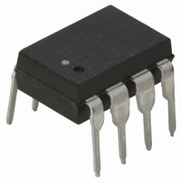
HCPL-7720-000E Avago Technologies US Inc., HCPL-7720-000E Datasheet - Page 14

HCPL-7720-000E
Manufacturer Part Number
HCPL-7720-000E
Description
OPTOCOUPLER CMOS 25MBD 8-DIP
Manufacturer
Avago Technologies US Inc.
Datasheet
1.HCPL-0720-000E.pdf
(19 pages)
Specifications of HCPL-7720-000E
Package / Case
8-DIP (0.300", 7.62mm)
Voltage - Isolation
3750Vrms
Number Of Channels
1, Unidirectional
Current - Output / Channel
10mA
Data Rate
25MBd
Propagation Delay High - Low @ If
20ns
Input Type
Logic
Output Type
Push-Pull, Totem-Pole
Mounting Type
Through Hole
Isolation Voltage
3750 Vrms
Maximum Continuous Output Current
10 mA
Maximum Fall Time
0.008 us
Maximum Forward Diode Current
10 mA
Output Device
Logic Gate Photo IC
Configuration
1 Channel
Maximum Baud Rate
25 MBd
Maximum Power Dissipation
150 mW
Maximum Operating Temperature
+ 85 C
Minimum Operating Temperature
- 40 C
No. Of Channels
1
Optocoupler Output Type
Gate Drive
Input Current
10µA
Output Voltage
5V
Opto Case Style
DIP
No. Of Pins
8
Common Mode Ratio
10000
Rohs Compliant
Yes
Lead Free Status / RoHS Status
Lead free / RoHS Compliant
Lead Free Status / RoHS Status
Lead free / RoHS Compliant, Lead free / RoHS Compliant
Other names
516-1689-5
Available stocks
Company
Part Number
Manufacturer
Quantity
Price
Company:
Part Number:
HCPL-7720-000E
Manufacturer:
AVAGO
Quantity:
5 000
Part Number:
HCPL-7720-000E
Manufacturer:
AVAGO/安华高
Quantity:
20 000
Optical Isolation for Field Bus Networks
To recognize the full benefits of these networks, each
recom mends providing galvanic isolation using Avago
optocouplers. Since network communication is bi-direc-
tional (involving receiving data from and transmitting
data onto the network), two Avago optocouplers are
needed. By providing galvanic isolation, data integrity is
retained via noise reduction and the elimination of false
signals. In addition, the network receives maximum pro-
tection from power system faults and ground loops.
Within an isolated node, such as the DeviceNet Node
shown in Figure 16, some of the node’s components are
referenced to a ground other than V- of the network.
14
DRAIN/SHIELD
Figure 16. Typical DeviceNet Node.
SIGNAL
POWER
NETWORK
SUPPLY
POWER
772x/072x
NODE/APP SPECIFIC
HCPL
TRANSCEIVER
uP/CAN
772x/072x
HCPL
5 V REG.
SUPPLY
LOCAL
NODE
AC LINE
V+ (SIGNAL)
V– (SIGNAL)
V+ (POWER)
V– (POWER)
GALVANIC
ISOLATION
BOUNDARY
These components could include such things as devices
with serial ports, parallel ports, RS232 and RS485 type
ports. As shown in Figure 16, power from the network is
used only for the transceiver and input (network) side of
the optocouplers.
Isolation of nodes connected to any of the three types of
digital field bus networks is best achieved by using the
HCPL-772X/072X optocouplers. For each network, the
HCPL-772X/072X satisify the critical propagation delay
and pulse width distortion require ments over the tem-
perature range of 0°C to +85°C, and power supply volt-
age range of 4.5 V to 5.5 V.


