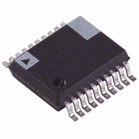
ADE7756ARS Analog Devices Inc, ADE7756ARS Datasheet - Page 25

ADE7756ARS
Manufacturer Part Number
ADE7756ARS
Description
IC ENERGY METERING 1PHASE 20SSOP
Manufacturer
Analog Devices Inc
Datasheet
1.ADE7756AN.pdf
(32 pages)
Specifications of ADE7756ARS
Rohs Status
RoHS non-compliant
Input Impedance
390 KOhm
Measurement Error
0.1%
Voltage - I/o High
2.4V
Voltage - I/o Low
0.8V
Current - Supply
3mA
Voltage - Supply
4.75 V ~ 5.25 V
Operating Temperature
-40°C ~ 85°C
Mounting Type
Surface Mount
Package / Case
20-SSOP (0.200", 5.30mm Width)
Meter Type
Single Phase
Lead Free Status / RoHS Status
Not Compliant
Available stocks
Company
Part Number
Manufacturer
Quantity
Price
Company:
Part Number:
ADE7756ARSZ
Manufacturer:
AD
Quantity:
17 677
Part Number:
ADE7756ARSZ
Manufacturer:
ADI/亚德诺
Quantity:
20 000
Assuming the meter is set up with a test current (basic current)
of 20 A and a line voltage of 220 V for calibration, the load is
calculated as 220 V × 20 A = 4.4 kW. Therefore the expected
output frequency on CF under this steady load condition would
be 4.4 × 0.8888 Hz = 3.9111 Hz.
Under these load conditions the transducers on Channel 1 and
Channel 2 should be selected such that the signal on the voltage
channel should see approximately half scale and the signal on
the current channel about 1/8 of full scale (assuming a maximum
current of 80A). The average value from LPF2 is calculated
as 3,276.81 decimal using the calibration mode as described
above. Then, using Equation 8 (Energy to Frequency Conver-
sion), the frequency under this load is calculated as:
However, this is the frequency with the contents of the CFDIV
and APGAIN registers equal to 000h. The desired frequency
out is 3.9111 Hz. Therefore the CF frequency must be divided
by 349.566/3.9111 Hz or 89.378 decimal. This is achieved by
loading the CF Divide register with 88 (or 58h)—Note the CF
frequency is divided by the contents of CFDIV + 1.
The fine adjustment of the output frequency can be made using
the Active Power Gain register. This register has a fine gain
adjustment of 0.0244%/LSB. With the CF Divide register con-
tents equal to 58h, the output frequency is given as 349.556 Hz/
89 = 3.9276 Hz. This setting has an error of 0.42%. This
error can be further reduced by writing –(0.21/0.0244) or –17 to
APGAIN[11:0] i.e., FEFh.
Calibrating CF is made easy by using the Calibration mode on
the ADE7756. The only critical part of the setup is that the line
frequency be exactly known. If this is not possible, it could be
measured by using the ZX output of the ADE7756.
Energy Meter Display
Besides the pulse output which is used to verify calibration, a
solid state energy meter will very often require some form of
display. The display should display the amount of energy con-
sumed in kWh (Kilowatt Hours). One convenient and simple
way to interface the ADE7756 to a display or energy register (e.g.,
MCU with nonvolatile memory) is to use CF. For example the
CF frequency could be calibrated to 1,000 imp/kWh. The MCU
would count pulses from CF. Every pulse would be equivalent
to 1 watt-hour. If more resolution is required the CF frequency
could be set to, say, 10,000 imp/kWh.
If more flexibility is required when monitoring energy usage, the
Active Energy register (AENERGY) can be used to calculate
energy. A full description of this register can be found in the
Energy Calculation section. The AENERGY register gives the
user both sign and magnitude information regarding energy
consumption. On completion of the CF frequency output cali-
bration, i.e., after the Active Power Gain (APGAIN) register has
been adjusted, a second calibration sequence can be initiated.
The purpose of this second calibration routine is to determine a
kWh/LSB coefficient for the AENERGY register. Once the
coefficient has been calculated the MCU can determine the
energy consumption at any time by reading the AENERGY
contents and multiplying by the coefficient to calculate kWh.
Frequency CF
(
)
=
3276 81 3 579545
.
×
2
.
25
MHz
=
349 566
.
Hz
CLKIN FREQUENCY
In this data sheet, the characteristics of the ADE7756 are shown
with CLKIN frequency equal to 3.579545 MHz. However, the
ADE7756 is designed to have the same accuracy at any CLKIN
frequency within the specified range. If the CLKIN frequency is
not 3.579545 MHz, various timing and filter characteristics will
need to be redefined with the new CLKIN frequency. For
example, the cut-off frequencies of all digital filters (LPF1,
LPF2, HPF1, etc.) will shift in proportion to the change in
CLKIN frequency according to the following equation:
The change of CLKIN frequency does not affect the timing
characteristics of the serial interface because the data transfer is
synchronized with serial clock signal (SCLK). But one needs to
observe the read/write timing of the serial data transfer-see
Timing Characteristics. Table III lists various timing changes
that are affected by CLKIN frequency.
APPLICATION INFORMATION
Application note AN-564 contains detail information on how
to design a ANSI Class 100 Watt-Hour meter based on the
ADE7756. It is available from the ADE7756 product home page
under the Application Note link. Figure 35 shows the block dia-
gram of the ADE7756 reference meter implemented in AN-564.
Parameter
Nyquist Frequency for CH 1 and 2 ADCs
PHCAL Resolution (Seconds per LSB)
Active Energy Register Update Rate (Hz)
Waveform Sampling Rate
(Number of Samples per Second)
Maximum ZXTOUT Period
New Frequency
220V
N
WAVSEL 1, 0 = 0
L1
LOAD
Table III. Frequency Dependencies of the
ADE7756 Parameters
L2
=
Original Frequency
0
1
1
CF
0
1
0
1
ADE7756
EEPROM
SPI BUS
×
CLKIN Frequency
3 579545
.
16 2 LCD DISPLAY
ADE7756
PIC16C62B
CLKIN
Dependency
CLKIN/8
16/CLKIN
CLKIN/4
CLKIN/128
CLKIN/256
CLKIN/512
CLKIN/1024
524,288/CLKIN
MHz
RS-232
(17)


