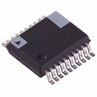
ADE7756ARS Analog Devices Inc, ADE7756ARS Datasheet - Page 19

ADE7756ARS
Manufacturer Part Number
ADE7756ARS
Description
IC ENERGY METERING 1PHASE 20SSOP
Manufacturer
Analog Devices Inc
Datasheet
1.ADE7756AN.pdf
(32 pages)
Specifications of ADE7756ARS
Rohs Status
RoHS non-compliant
Input Impedance
390 KOhm
Measurement Error
0.1%
Voltage - I/o High
2.4V
Voltage - I/o Low
0.8V
Current - Supply
3mA
Voltage - Supply
4.75 V ~ 5.25 V
Operating Temperature
-40°C ~ 85°C
Mounting Type
Surface Mount
Package / Case
20-SSOP (0.200", 5.30mm Width)
Meter Type
Single Phase
Lead Free Status / RoHS Status
Not Compliant
Available stocks
Company
Part Number
Manufacturer
Quantity
Price
Company:
Part Number:
ADE7756ARSZ
Manufacturer:
AD
Quantity:
17 677
Part Number:
ADE7756ARSZ
Manufacturer:
ADI/亚德诺
Quantity:
20 000
CHANNEL 2 ADC
Channel 2 Sampling
In Channel 2 waveform sampling mode (MODE[14:13] = 1,1
and WSMP = 1) the ADC output code scaling for Channel 2 is
the same as Channel 1, i.e., the output swings between D7AE1h
(–165,151) and 2851Fh (+165,151)—see ADC Channel 1 sec-
tion. However, before being passed to the Waveform register, the
ADC output is passed through a single-pole, low-pass filter
with a cutoff frequency of 156 Hz. The plots in Figure 20
shows the magnitude and phase response of this filter.
DOUT
SCLK
IRQ
DIN
–20
–40
–60
–80
0
10
1
16 s
SAMPLING RATE
(27.9kSPS, 14kSPS, 7kSPS OR 3.5kSPS)
READ FROM WAVEFORM
0 0 0 01 HEX
(60Hz, –21.04 )
FREQUENCY – Hz
10
2
SIGN
(60Hz, –0.6dB)
CHANNEL 1 DATA – 20 BITS
10
3
0
–20
–40
This has the effect of attenuating the signal. For example, if the
line frequency is 60 Hz, the signal at the output of LPF1 will be
attenuated by 30%.
Note that LPF1 does not affect the power calculation. The signal
processing chain in Channel 2 is illustrated in Figure 21. Unlike
Channel 1, Channel 2 has only one analog input range (1 V
differential). However, like Channel 1, Channel 2 does have a PGA
with gain selections of 1, 2, 4, 8, and 16. For energy measure-
ment, the output of the ADC is passed directly to the multiplier
and is not filtered. An HPF is not required to remove any dc
offset since it is only required to remove the offset from one chan-
nel to eliminate errors due to offsets in the power calculation.
When in waveform sample mode, one of four output sample
rates can be chosen by using Bits 11 and 12 of the Mode regis-
ter. The available output sample rates are 27.9 kSPS, 14 kSPS,
7 kSPS or 3.5 kSPS—see Mode Register section. The interrupt
request output IRQ signals a new sample availability by going
active low. The timing is the same as that for Channel 1 and is
shown in Figure 19.
0.25V, 0.125V,
V2
1V, 0.5V,
0.0625V
V2N
V2P
0V
| ( )|
H f
V1
x1, x2, x4,
x8, x16
ANALOG INPUT
RANGE
GAIN[7:5]
PGA2
=
60Hz
1
+
2.42V
156
REFERENCE
60
E3C6Ah
D7AE1h
1C396h
C0000h
2851Fh
40000h
00000h
1
ADC2
Hz
Hz
LPF OUTPUT
WORD RANGE
2
1
=
–63% TO + 63% FS
0 93
.
60Hz
+63% FS
+44% FS
–44% FS
–63% FS
–FS
+FS
LPF1
=
ADE7756
– .
0 6
20
dB
TO
WAVEFORM
REGISTER
TO
MULTIPLIER


