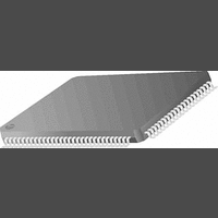
PC87393VJG National Semiconductor, PC87393VJG Datasheet - Page 86

PC87393VJG
Manufacturer Part Number
PC87393VJG
Description
IC, SUPER I/O DEVICE, TQFP-100
Manufacturer
National Semiconductor
Specifications of PC87393VJG
Data Rate
2Mbps
Supply Voltage Range
3V to 3.6V
Logic Case Style
TQFP
No. Of Pins
100
Operating Temperature Range
0°C to +70°C
Termination Type
SMD
Transceiver Type
Interface
Rohs Compliant
No
Available stocks
Company
Part Number
Manufacturer
Quantity
Price
Part Number:
PC87393VJG
Manufacturer:
NS/国半
Quantity:
20 000
www.national.com
5.0 Game Port (GMP)
A simple push-button mechanism is usually used to implement the game device buttons. The status of each button is sensed
by the Game Port via the JOYnBTN0,1 pins as either high or low, and reflected by the GMPLST register. It is the responsi-
bility of the software to determine the actual status of the buttons according to their polarity, which depends on the specific
implementation of the system and the game device.
5.2.4
The Game Port can be used to monitor the position and button status indicators in one of the following operation modes:
Legacy Mode
Legacy mode is enabled when bit 0 of the GMPCTL register is set to 0, which is its default state.
In this mode, the game device indicators are monitored by polling their momentary status via the Game Port Legacy Status
register (GMPLST, see Section 5.3.3).
The process of reading the position status of the game device(s) is initiated by performing a write access to offset 1 in the
Game Port address space. This write access causes the Game Port to release the JOYnX,Y pins. When a JOYnX,Y pin is
released, the corresponding bit in the GMPLST register is set to 1. To capture the position indicated by the game device,
the software must poll the GMPLST register and measure the time it takes for the JOYnX,Y to go high. This measurement
should be performed by measuring the time during which an axis bit is 1.
Reading the status of the buttons of the game device is done by polling the GMPLST register and looking for changes in the
bits reflecting the status of the JOYnBTN0,1 pins.
No debounce of the input signals is performed by the Game Port in Legacy mode. It is the responsibility of the software to
implement such debounce, if necessary.
Enhanced Mode
Enhanced mode is enabled when bit 0 of the GMPCTL register is set to 1.
In Enhanced mode, the Game Port hardware monitors the status indicators of the game device(s), and provides processed
data that can be easily used by software to determine the complete status of the game device.
The process of reading the position status of the game device(s) is initiated as in Legacy mode. However, in Enhanced mode
the Game Port hardware measures the C
lines (two lines per game device) has a dedicated counter.
Once the Game Port releases the JOYnX,Y to go high, each one of the counters starts counting until its associated axis
status line reaches the voltage level of logic 1.
When a position counter of a game device stops counting, its associated Position Counter Ready bit in the GMPXST register
is set. In this case, the software must wait until the counters associated with the game device are ready, and then read their
values. The least significant byte of a position counter should be read first. The full, 16-bit count value should be calculated
as follows:
The software must calibrate itself according to the actual count values acquired when the game device was set to indicate
its extreme horizontal and vertical positions.
If a position counter has reached the full count of FFFFh, this counter has overflowed; i.e., it has reached its full count before
the corresponding axis indicator has reached the level of logic 1. In such a case, the software must decide what to do.
The Game Port supports the following clock frequencies for operating the position counters:
The clock frequency for the position counter of each game device is configured via the GMPCTL register and should be set
by the software to match the physical components of the external game device interface circuitry. The desired position of
the counter frequency should be set before initiating a position status reading process.
Reading the status of the buttons of the game device(s) is performed as in Legacy mode. In addition, an optional debouncer
of 16 msec is implemented on each button status input. The debouncers are disabled by default and may be enabled by
software via the GMPCTL register.
Legacy mode
Enhanced mode.
1 MHz clock (default)
500 KHz clock.
Operation Modes
where:
GMPnX/YL indicates the low byte of the position counter of device n (either X or Y axis)
GMPnY/HL indicates the high byte of the position counter of device n (either X or Y axis)
(Continued)
X/Y Position Count = GMPnX/YL + (GMPnX
X/Y
charging time using four 16-bit up-counters. Each one of the four axis status
86
/YH *
256)


