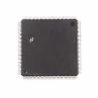
DP83907VF National Semiconductor, DP83907VF Datasheet - Page 24

DP83907VF
Manufacturer Part Number
DP83907VF
Description
IC CONTROLLR AT/LANII TP 160PQFP
Manufacturer
National Semiconductor
Datasheet
1.DP83907VF.pdf
(70 pages)
Specifications of DP83907VF
Controller Type
Network Interface Controller (NIC)
Interface
Twisted Pair
Voltage - Supply
4.75 V ~ 5.25 V
Current - Supply
150mA
Operating Temperature
0°C ~ 70°C
Mounting Type
Surface Mount
Package / Case
160-MQFP, 160-PQFP
Lead Free Status / RoHS Status
Contains lead / RoHS non-compliant
Other names
*DP83907VF
Available stocks
Company
Part Number
Manufacturer
Quantity
Price
Company:
Part Number:
DP83907VF
Manufacturer:
NSC
Quantity:
5 510
0–1
Bit
5 0 Register Descriptions
MODE CONFIGURATION REGISTER B
To prevent any accidental writes of this register it is ‘‘hidden’’ behind a previously unused register Register 0BH in the
DP83907’s Page 0 of registers was previously reserved on a read Now Configuration Register B can be read at that address
and can be written to by following a read to 0BH with a write to 0BH If any other DP83907 register accesses take place between
the read and the write then the write to 0BH will access the Remote Byte Count Register 1 Care should be taken when
writing to this register as GDLINK and BE are not simple read write bits e g the user can not change the physical layer by
reading B or-ing the returned value with the bits to be set and writing this value to B This could inadvertently disable link
integrity generation and clear a bus error indication before it was noted
2
3
4
5
6
7
IO16CON
EELOAD
PHYS0 –
GDLINK
Symbol
PHYS1
BPWR
RES
BE
PHYSICAL LAYER INTERFACE These 2 bits determine which type of physical interface the DP83907 is
using The 2 TPI interfaces use twisted pair outputs and inputs while the other 2 interfaces use the AUI
outputs and inputs In 10BASE5 mode the THICK THIN output pin is driven low in 10BASE2 mode it is
driven high This can be used to enable the DC-DC converter required by the 10BASE2 specification to
provide electrical isolation The Non spec TPI mode is a twisted pair mode with reduced receive squelch
levels This allows the use of longer cable lengths than specified in the twisted pair specification or the use
of cable with higher losses
Bit 1 0
GOOD LINK When a 1 is written to this bit the link test pulse generation and integrity checking is disabled
When this bit is read it will indicate the link status reflecting the value shown on the LED output It is 0 if the
DP83907 is in AUI mode or if link testing is enabled and the link integrity is bad (i e the twisted pair link has
been broken) It is 1 if the DP83907 is in TPI mode link integrity checking is enabled and the link integrity is
good (i e the twisted pair link has not been broken) or if the link testing is disabled
IO16 CONTROL When this bit is set high the DP83907 generates IO16 after IORD or IOWR go active If
low this output is generated only on address decode
RESERVED This bit must be set low for normal operation
BUS ERROR This bit shows that the DP83907 has detected a bus error condition This will go high if the
DP83907 attempts to insert wait states into a system access and the system terminates the cycle without
inserting the wait states Writing a one to this bit clears it to zero Writing a zero has no effect
BOOT PROM WRITE When this bit is low no write cycles are generated to the boot PROM
EEPROM LOAD Writing a 1 to this bit enables the EEPROM load algorithm as detailed in Section 4 This
bit should not be configured to be high either from switches or an EEPROM
0 0
0 1
1 0
1 1
EELOAD
7
TPI (10BASE-T Compatible Squelch Level)
Thin Ethernet (10BASE2)
Thick Ethernet (10BASE5) (AUI Port)
TPI (Reduced Squelch Level)
BPWR
6
(Continued)
BE
5
RES
4
IO16CON
24
3
Function
GDLINK
2
PHYS1
1
PHYS0
0


