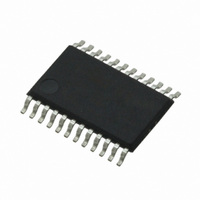
CS4270-DZZ Cirrus Logic Inc, CS4270-DZZ Datasheet - Page 31

CS4270-DZZ
Manufacturer Part Number
CS4270-DZZ
Description
IC CODEC 24BIT 105DB 24TSSOP
Manufacturer
Cirrus Logic Inc
Type
Stereo Audior
Specifications of CS4270-DZZ
Data Interface
Serial
Resolution (bits)
24 b
Number Of Adcs / Dacs
2 / 2
Sigma Delta
Yes
Dynamic Range, Adcs / Dacs (db) Typ
105 / 105
Voltage - Supply, Analog
3.1 V ~ 5.25 V
Voltage - Supply, Digital
3.1 V ~ 5.25 V
Operating Temperature
-40°C ~ 85°C
Mounting Type
Surface Mount
Package / Case
24-TSSOP
Audio Codec Type
Stereo
No. Of Adcs
1
No. Of Dacs
1
No. Of Input Channels
3
No. Of Output Channels
3
Adc / Dac Resolution
24bit
Sampling Rate
216kSPS
Ic Interface Type
I2C
Lead Free Status / RoHS Status
Lead free / RoHS Compliant
For Use With
598-1002 - BOARD EVAL FOR CS4270 CODEC
Lead Free Status / RoHS Status
Lead free / RoHS Compliant, Lead free / RoHS Compliant
Other names
598-1622
Available stocks
Company
Part Number
Manufacturer
Quantity
Price
Company:
Part Number:
CS4270-DZZ
Manufacturer:
CIRRUS
Quantity:
9
Company:
Part Number:
CS4270-DZZ
Manufacturer:
CIRRUS
Quantity:
62
DS686PP1
5.6
5.7
Synchronization of Multiple Devices
Grounding and Power Supply Decoupling
In systems where multiple ADCs are required, care must be taken to achieve simultaneous sampling. To
ensure synchronous sampling, the MCLK and LRCK must be the same for all of the CS4270’s in the sys-
tem. If only one MCLK source is needed, one solution is to place one CS4270 in Master Mode, and slave
all of the other CS4270’s to the one master. If multiple MCLK sources are needed, a possible solution
would be to supply all clocks from the same external source and time the CS4270 reset with the inactive
edge of MCLK. This will ensure that all converters begin sampling on the same clock edge.
As with any high resolution converter, the CS4270 requires careful attention to power supply and ground-
ing arrangements if its potential performance is to be realized.
arrangements, with VA and VD connected to clean supplies. VD, which powers the digital filter, may be
run from the system digital supply (VD) or may be powered from the analog supply (VA) via a resistor. In
this case, no additional devices should be powered from VD. Power supply decoupling capacitors should
be as near to the CS4270 as possible, with the low value ceramic capacitor being the nearest. All signals,
especially clocks, should be kept away from the VREF and VCOM pins in order to avoid unwanted cou-
pling into the modulators. The VREF and VCOM decoupling capacitors, particularly the 0.1 µF, must be
positioned to minimize the electrical path from VREF and AGND. The CDB4270 evaluation board dem-
onstrates the optimum layout and power supply arrangements. To minimize digital noise, connect the
CS4270 digital outputs only to CMOS inputs.
CS4270
AOUTx
MUTEx
Figure 20. Suggested Active-Low Mute Circuit
LPF
+V
-V
EE
EE
Couple
MMUN2111LT1
AC
+V
A
-V
EE
10 kΩ
560 Ω
2 kΩ
Figure 1
shows the recommended power
47 kΩ
Audio
Out
CS4270
31


