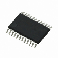
CS4270-DZZ Cirrus Logic Inc, CS4270-DZZ Datasheet - Page 29

CS4270-DZZ
Manufacturer Part Number
CS4270-DZZ
Description
IC CODEC 24BIT 105DB 24TSSOP
Manufacturer
Cirrus Logic Inc
Type
Stereo Audior
Specifications of CS4270-DZZ
Data Interface
Serial
Resolution (bits)
24 b
Number Of Adcs / Dacs
2 / 2
Sigma Delta
Yes
Dynamic Range, Adcs / Dacs (db) Typ
105 / 105
Voltage - Supply, Analog
3.1 V ~ 5.25 V
Voltage - Supply, Digital
3.1 V ~ 5.25 V
Operating Temperature
-40°C ~ 85°C
Mounting Type
Surface Mount
Package / Case
24-TSSOP
Audio Codec Type
Stereo
No. Of Adcs
1
No. Of Dacs
1
No. Of Input Channels
3
No. Of Output Channels
3
Adc / Dac Resolution
24bit
Sampling Rate
216kSPS
Ic Interface Type
I2C
Lead Free Status / RoHS Status
Lead free / RoHS Compliant
For Use With
598-1002 - BOARD EVAL FOR CS4270 CODEC
Lead Free Status / RoHS Status
Lead free / RoHS Compliant, Lead free / RoHS Compliant
Other names
598-1622
Available stocks
Company
Part Number
Manufacturer
Quantity
Price
Company:
Part Number:
CS4270-DZZ
Manufacturer:
CIRRUS
Quantity:
9
Company:
Part Number:
CS4270-DZZ
Manufacturer:
CIRRUS
Quantity:
62
DS686PP1
Attenuation: The required attenuation factor depends on the magnitude of the input signal. For
VA = 5 V, the full-scale input voltage equals 1 Vrms. The full-scale input voltage scales with VA as indi-
cated on pages 13 and 14. The user should select values for R1 and R2 such that the magnitude of the
incoming signal multiplied by the attenuation factor is less than or equal to the full-scale input voltage of
the device.
Input Impedance: Input impedance is the impedance from the signal source to the ADC analog input
pins.
Figure 18
will attenuate a typical line level voltage, 2 Vrms, to the full-scale input of the ADC, 1 Vrms when VA = 5
V and is the maximum source impedance for the ADC specifications listed in this Data Sheet.
Table 6
illustrates an example configuration using two 2 kΩ resistors in place of R1 and R2. This circuit
shows the input parameters and the associated design equations.
Figure 17. A/D Dynamic Range vrs. Input Source Resistance
Source Impedance
Attenuation Factor
Table 6. Analog Input Design Parameters
Input Impedance
(
------------------------ -
------------------------ -
(
(
R1 R2
R1
R1
R1
(
R2
×
+
+
+
R2
R2
R2
)
)
)
)
CS4270
29


