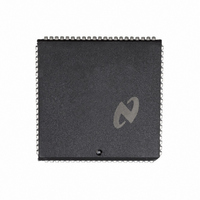
DP8344BV National Semiconductor, DP8344BV Datasheet - Page 28

DP8344BV
Manufacturer Part Number
DP8344BV
Description
IC BIPHASE COMM PROCESSR 84-PLCC
Manufacturer
National Semiconductor
Datasheet
1.DP8344BV.pdf
(184 pages)
Specifications of DP8344BV
Processor Type
8-Bit RISC
Speed
20MHz
Voltage
4.5 ~ 5.5V
Mounting Type
Surface Mount
Package / Case
84-PLCC
Operating Supply Voltage (typ)
5V
Operating Supply Voltage (max)
5.5V
Operating Supply Voltage (min)
4.5V
Mounting
Surface Mount
Operating Temperature (max)
70C
Operating Temperature (min)
0C
Operating Temperature Classification
Commercial
Lead Free Status / RoHS Status
Contains lead / RoHS non-compliant
Features
-
Lead Free Status / Rohs Status
Not Compliant
Other names
*DP8344BV
Available stocks
Company
Part Number
Manufacturer
Quantity
Price
Company:
Part Number:
DP8344BV
Manufacturer:
NSC
Quantity:
5 510
Part Number:
DP8344BV
Manufacturer:
NS/国半
Quantity:
20 000
2 0 CPU Description
2 2 CPU FUNCTIONAL DESCRIPTION
2 2 1 ALU
The BCP provides a full function high speed 8-bit Arithmetic
Logic Unit (ALU) with full carry look ahead signed arithme-
tic and overflow decision capabilities The ALU can perform
six arithmetic nine logic one rotate and two shift operations
on binary data Full access is provided to all CPU registers
as both source and destination operands and using the in-
direct addressing mode results may be placed directly into
data memory All operations which have an internal destina-
tion (register addressing) are completed in two (2) T-states
External destination operations (indirect addressing to data
memory) complete in three (3) T-states
Arithmetic operations include addition with or without carry
and subtraction with or without borrow (represented by car-
ry) Subtractions are performed using 2’s complement addi-
tion to accommodate signed operands The subtrahend is
converted to its 2’s complement equivalent by the ALU and
then added to the minuend The result is left in 2’s comple-
ment form
The remaining ALU operations include full logic shift and
rotate operations The logic functions include Complement
AND OR Exclusive-OR Compare and Bit Test Zero
through seven bit right and left shift operations are provided
along with a zero through seven bit right rotate operation
Note that the shift and rotate operations may only be per-
formed on a register which is both the source and destina-
tion (See the Instruction Set Overview section for detailed
descriptions of these operations )
The BCP ALU provides the programmer with four instruction
result status bits for conditional operations These bits
(known as condition code flags) indicate the status (or con-
dition) of the destination byte produced by certain instruc-
tions Not all instructions have an affect on every status flag
(See the Instruction Set Reference section for the specific
details on what status flags a given instruction affects )
These flags are held in the Condition Code Register
where
If an instruction is documented as affecting a given flag
then the flags are set (to 1) or cleared (to 0) under the
following conditions
N
CCR
N
C
V
Z
e
e
e
FIGURE 2-7 Condition Code Register ALU Flags
e
The Negative flag is set if the most significant bit
(MSB) of the result is one (1) otherwise it is cleared
This flag represents the sign of the result if it is inter-
preted as a 2’s complement number
TO
Negative
Carry
Overflow
Zero
7
see Figure 2-7
RR
6
RW
5
BIRQ
4
N
3
(Continued)
V
2
1
C
0
Z
28
C
V
Z
1
Overflow is set whenever the result of an arithmetic or
compare operation on signed operands is not repre-
sentable by the operand size thereby producing an
incorrect result For example the addition of the two
signed negative numbers in Figure 2-8a would set V
since the correct representation of the result both
sign and magnitude is not possible in 8 bits On the
other hand in Figure 2-8b and 2-8c V would be
cleared because the results are correctly represented
in both sign and magnitude It is important to remem-
ber that Overflow is only meaningful in signed arith-
metic and that it is the programmer’s responsibility to
determine if a given operation involves signed or un-
signed values
The Zero flag is set only when an operation produces
an all bits cleared result (i e a zero) In all other con-
ditions Z is cleared
FIGURE 2 8 Carry and Overflow Calculations
The Carry flag is set if
a) An addition operation generates a carry see Fig-
b) A subtract or compare operation generates a bor-
c) The last bit shifted out during a shift operation (in
d) The last bit rotated by the rotate operation is a one
In all other conditions C is cleared
a
ure 2-8a
row see Figure 2-8b
either direction) is a one (1) see Figure 2-9
(1) see Figure 2-10
FIGURE 2-10 Rotate’s Effect on Carry
11101010
10001100
01110110
FIGURE 2-9 Shifts’ Effect on Carry
C
V
(a)
e
e
1
1
1
b
10111010
11000100
11110110
C
V
(b)
e
e
1
0
1
a
11011100
01100011
00111111
TL F 9336 – D4
C
TL F 9336 – D3
V
(c)
e
e
1
0


