ADSP-21375KSWZ-2B Analog Devices Inc, ADSP-21375KSWZ-2B Datasheet - Page 31
ADSP-21375KSWZ-2B
Manufacturer Part Number
ADSP-21375KSWZ-2B
Description
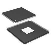
IC DSP 32BIT 266MHZ 208-MQFP
Manufacturer
Analog Devices Inc
Series
SHARC®r
Type
Floating Pointr
Specifications of ADSP-21375KSWZ-2B
Package / Case
208-LQFP
Interface
DAI, DPI
Operating Temperature
0°C ~ 70°C
Clock Rate
266MHz
Non-volatile Memory
ROM (256 kB)
On-chip Ram
64kB
Voltage - I/o
3.30V
Voltage - Core
1.20V
Mounting Type
Surface Mount
Svhc
No SVHC (18-Jun-2010)
Base Number
21375
Core Frequency Typ
266MHz
Dsp Type
Floating Point
Mmac
532
No. Of Pins
208
Interface Type
SPI, UART
Rohs Compliant
Yes
Operating Temperature Range
0°C To +70°C
Package
208LQFP EP
Numeric And Arithmetic Format
Floating-Point
Maximum Speed
266 MHz
Ram Size
64 KB
Device Million Instructions Per Second
266 MIPS
Lead Free Status / RoHS Status
Lead free / RoHS Compliant
Available stocks
Company
Part Number
Manufacturer
Quantity
Price
Company:

Part Number:
ADSP-21375KSWZ-2B
Manufacturer:
BB
Quantity:
116
Company:
Part Number:
ADSP-21375KSWZ-2B
Manufacturer:
Analog Devices Inc
Quantity:
10 000


Serial Ports
To determine whether communication is possible between two
devices at clock speed n, the following specifications must be
confirmed: 1) frame sync delay and frame sync setup and hold,
2) data delay and data setup and hold, and 3) SCLK width.
Table 29. Serial Ports—External Clock
1
2
Table 30. Serial Ports—Internal Clock
1
2
3
Parameter
Timing Requirements
t
t
t
t
t
t
Switching Characteristics
t
t
t
t
Referenced to sample edge.
Referenced to drive edge.
Parameter
Timing Requirements
t
t
t
t
Switching Characteristics
t
t
t
t
t
t
t
Referenced to the sample edge.
Referenced to drive edge.
Minimum SPORT divisor register value.
SFSE
HFSE
SDRE
HDRE
SCLKW
SCLK
DFSE
HOFSE
DDTE
HDTE
SFSI
HFSI
SDRI
HDRI
DFSI
HOFSI
DFSIR
HOFSIR
DDTI
HDTI
SCKLIW
1
1
1
1
2
2
2
1
1
2
1
2
2
1
2
2
2
2
3
FS Setup Before SCLK
(Externally Generated FS in either Transmit or Receive Mode)
FS Hold After SCLK
(Externally Generated FS in either Transmit or Receive Mode)
Receive Data Setup Before Receive SCLK
Receive Data Hold After SCLK
SCLK Width
SCLK Period
FS Delay After SCLK
(Internally Generated FS in either Transmit or Receive Mode)
FS Hold After SCLK
(Internally Generated FS in either Transmit or Receive Mode)
Transmit Data Delay After Transmit SCLK
Transmit Data Hold After Transmit SCLK
FS Setup Before SCLK
(Externally Generated FS in either Transmit or Receive Mode)
FS Hold After SCLK
(Externally Generated FS in either Transmit or Receive Mode)
Receive Data Setup Before SCLK
Receive Data Hold After SCLK
FS Delay After SCLK (Internally Generated FS in Transmit Mode)
FS Hold After SCLK (Internally Generated FS in Transmit Mode)
FS Delay After SCLK (Internally Generated FS in Receive Mode)
FS Hold After SCLK (Internally Generated FS in Receive Mode)
Transmit Data Delay After SCLK
Transmit Data Hold After SCLK
Transmit or Receive SCLK Width
Rev. B | Page 31 of 52 | June 2008
Serial port signals (SCLK, FS, Data Channel A, Data Channel B)
are routed to the DAI_P20–1 pins using the SRU. Therefore, the
timing specifications provided below are valid at the
DAI_P20–1 pins.
1.2 V, 266 MHz
Min
2.5
2.5
2.5
2.5
10
20
2
2
1.2 V, 266 MHz
Min
7
2.5
7
2.5
–1.0
–1.0
–1.0
0.5t
ADSP-21371/ADSP-21375
SCLK
– 2
Max
10.5
11
Max
4
10.7
3.6
0.5t
SCLK
+ 2
Unit
ns
ns
ns
ns
ns
ns
ns
ns
ns
ns
Unit
ns
ns
ns
ns
ns
ns
ns
ns
ns
ns
ns
Related parts for ADSP-21375KSWZ-2B
Image
Part Number
Description
Manufacturer
Datasheet
Request
R

Part Number:
Description:
±1.7g Dual-Axis IMEMS Accelerometer Evaluation Board
Manufacturer:
Analog Devices Inc
Datasheet:

Part Number:
Description:
Inertial Sensor Evaluation System
Manufacturer:
Analog Devices Inc
Datasheet:
Part Number:
Description:
Manufacturer:
Analog Devices Inc
Datasheet:
Part Number:
Description:
Manufacturer:
Analog Devices Inc
Datasheet:
Part Number:
Description:
Manufacturer:
Analog Devices Inc
Datasheet:
Part Number:
Description:
Manufacturer:
Analog Devices Inc
Datasheet:
Part Number:
Description:
Manufacturer:
Analog Devices Inc
Datasheet:
Part Number:
Description:
Manufacturer:
Analog Devices Inc
Datasheet:
Part Number:
Description:
Manufacturer:
Analog Devices Inc
Datasheet:
Part Number:
Description:
Manufacturer:
Analog Devices Inc
Datasheet:
Part Number:
Description:
Manufacturer:
Analog Devices Inc
Datasheet:
Part Number:
Description:
Manufacturer:
Analog Devices Inc
Datasheet:
Part Number:
Description:
Manufacturer:
Analog Devices Inc
Datasheet: