ADSP-21375KSWZ-2B Analog Devices Inc, ADSP-21375KSWZ-2B Datasheet - Page 14
ADSP-21375KSWZ-2B
Manufacturer Part Number
ADSP-21375KSWZ-2B
Description
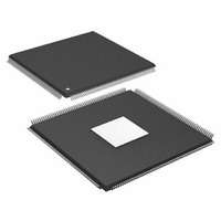
IC DSP 32BIT 266MHZ 208-MQFP
Manufacturer
Analog Devices Inc
Series
SHARC®r
Type
Floating Pointr
Specifications of ADSP-21375KSWZ-2B
Package / Case
208-LQFP
Interface
DAI, DPI
Operating Temperature
0°C ~ 70°C
Clock Rate
266MHz
Non-volatile Memory
ROM (256 kB)
On-chip Ram
64kB
Voltage - I/o
3.30V
Voltage - Core
1.20V
Mounting Type
Surface Mount
Svhc
No SVHC (18-Jun-2010)
Base Number
21375
Core Frequency Typ
266MHz
Dsp Type
Floating Point
Mmac
532
No. Of Pins
208
Interface Type
SPI, UART
Rohs Compliant
Yes
Operating Temperature Range
0°C To +70°C
Package
208LQFP EP
Numeric And Arithmetic Format
Floating-Point
Maximum Speed
266 MHz
Ram Size
64 KB
Device Million Instructions Per Second
266 MIPS
Lead Free Status / RoHS Status
Lead free / RoHS Compliant
Available stocks
Company
Part Number
Manufacturer
Quantity
Price
Company:

Part Number:
ADSP-21375KSWZ-2B
Manufacturer:
BB
Quantity:
116
Company:
Part Number:
ADSP-21375KSWZ-2B
Manufacturer:
Analog Devices Inc
Quantity:
10 000


ADSP-21371/ADSP-21375
Table 6. Pin List (Continued)
1
Name
FLAG[0]/IRQ0
FLAG[1]/IRQ1
FLAG[2]/IRQ2/
MS2
FLAG[3]/TIMEXP/
MS3
TDI
TDO
TMS
TCK
TRST
EMU
CLK_CFG
BOOT_CFG
RESET
XTAL
CLKIN
CLKOUT/
RESETOUT/
RUNRSTIN
Pull-up can be enabled/disabled, value of pull-up cannot be programmed.
1–0
1–0
Type
I/O
I/O
I/O with
programmable pu
(for MS mode)
I/O with
programmable pu
(for MS mode)
I (pu)
O/T
I (pu)
I
I (pu)
O/T (pu)
I
I
I
O
I
I/O (pu)
State During
and After Reset Description
High-Z/high-Z
High-Z/high-Z
High-Z/high-Z
High-Z/high-Z
Rev. B | Page 14 of 52 | June 2008
FLAG0/Interrupt Request0.
FLAG1/Interrupt Request1.
FLAG2/Interrupt Request/Memory Select2.
FLAG3/Timer Expired/Memory Select3.
Test Data Input (JTAG). Provides serial data for the boundary scan logic. TDI has a
22.5 kΩ internal pull-up resistor.
Test Data Output (JTAG). Serial scan output of the boundary scan path.
Test Mode Select (JTAG). Used to control the test state machine. TMS has a 22.5 kΩ
internal pull-up resistor.
Test Clock (JTAG). Provides a clock for JTAG boundary scan. TCK must be asserted (pulsed
low) after power-up or held low for proper operation of the ADSP-21371/ADSP-21375.
Test Reset (JTAG). Resets the test state machine. TRST must be asserted (pulsed low) after
power-up or held low for proper operation of the ADSP-21371/ADSP-21375. TRST has a
22.5 kΩ internal pull-up resistor.
Emulation Status. Must be connected to the ADSP-21371/ADSP-21375 Analog Devices
DSP Tools product line of JTAG emulators target board connector only. EMU has a 22.5 kΩ
internal pull-up resistor.
Core to CLKIN Ratio Control. These pins set the start up clock frequency. See
a description of the clock configuration modes.
Note that the operating frequency can be changed by programming the PLL multiplier
and divider in the PMCTL register at any time after the core comes out of reset.
Boot Configuration Select. These pins select the boot mode for the processor. The
BOOTCFG pins must be valid before reset is asserted. See
boot modes.
Processor Reset. Resets the ADSP-21371/ADSP-21375 to a known state. Upon deasser-
tion, there is a 4096 CLKIN cycle latency for the PLL to lock. After this time, the core begins
program execution from the hardware reset vector address. The RESET input must be
asserted (low) at power-up.
Crystal Oscillator Terminal. Used in conjunction with CLKIN to drive an external crystal.
Local Clock In. Used in conjunction with XTAL. CLKIN is the ADSP-21371/ADSP-21375
clock input. It configures the ADSP-21371/ADSP-21375 to use either its internal clock
generator or an external clock source. Connecting the necessary components to CLKIN
and XTAL enables the internal clock generator. Connecting the external clock to CLKIN
while leaving XTAL unconnected configures the ADSP-21371/ADSP-21375 to use the
external clock source such as an external clock oscillator. CLKIN may not be halted,
changed, or operated below the specified frequency.
Clock Out/Reset Out/Running Reset In. The functionality can be switched between the
PLL output clock and reset out by setting Bit 12 of the PMCTL register. The default is reset
out. This pin also has a third function as RUNRSTIN. The functionality of which is enabled
by setting Bit 0 of the RUNRSTCTL register. For more information, see the
ADSP-2136x SHARC Processor Hardware Reference for the ADSP-21367/8/9 Processors.
Table 9
for a description of the
Table 10
for
Related parts for ADSP-21375KSWZ-2B
Image
Part Number
Description
Manufacturer
Datasheet
Request
R

Part Number:
Description:
±1.7g Dual-Axis IMEMS Accelerometer Evaluation Board
Manufacturer:
Analog Devices Inc
Datasheet:

Part Number:
Description:
Inertial Sensor Evaluation System
Manufacturer:
Analog Devices Inc
Datasheet:
Part Number:
Description:
Manufacturer:
Analog Devices Inc
Datasheet:
Part Number:
Description:
Manufacturer:
Analog Devices Inc
Datasheet:
Part Number:
Description:
Manufacturer:
Analog Devices Inc
Datasheet:
Part Number:
Description:
Manufacturer:
Analog Devices Inc
Datasheet:
Part Number:
Description:
Manufacturer:
Analog Devices Inc
Datasheet:
Part Number:
Description:
Manufacturer:
Analog Devices Inc
Datasheet:
Part Number:
Description:
Manufacturer:
Analog Devices Inc
Datasheet:
Part Number:
Description:
Manufacturer:
Analog Devices Inc
Datasheet:
Part Number:
Description:
Manufacturer:
Analog Devices Inc
Datasheet:
Part Number:
Description:
Manufacturer:
Analog Devices Inc
Datasheet:
Part Number:
Description:
Manufacturer:
Analog Devices Inc
Datasheet: