NTHD3102CT1G ON Semiconductor, NTHD3102CT1G Datasheet
NTHD3102CT1G
Specifications of NTHD3102CT1G
NTHD3102CT1GOSTR
Available stocks


Related parts for NTHD3102CT1G

NTHD3102CT1G Summary of contents
Page 1
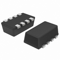
NTHD3102C Power MOSFET Complementary +5.5 A /−4.2 A, ChipFETt Features • Complementary N−Channel and P−Channel MOSFET • Small Size, 40% Smaller than TSOP−6 Package • Leadless SMD Package Provides Great Thermal Characteristics • Leading Edge Trench Technology for ...
Page 2
MAXIMUM RATINGS (continued N−Channel Continuous Drain Current (Note 3) P−Channel Continuous Drain Current (Note 3) Power Dissipation (Note 3) Pulsed Drain Current Operating Junction and Storage Temperature Source Current (Body Diode) Lead Temperature for Soldering Purposes (1/8″ from ...
Page 3
ELECTRICAL CHARACTERISTICS Parameter ON CHARACTERISTICS (Note 5) Gate Threshold Voltage Drain−to−Source On Resistance Forward Transconductance CHARGES, CAPACITANCES AND GATE RESISTANCE Input Capacitance Output Capacitance Reverse Transfer Capacitance Total Gate Charge Threshold Gate Charge Gate−to−Source Charge Gate−to−Drain Charge SWITCHING CHARACTERISTICS (Note ...
Page 4
ELECTRICAL CHARACTERISTICS Parameter DRAIN−SOURCE DIODE CHARACTERISTICS Forward Diode Voltage Reverse Recovery Time Charge Time Discharge Time Reverse Recovery Charge NTHD3102C (continued 25°C unless otherwise noted) J Symbol N/P Test Conditions ° ...
Page 5
TYPICAL N−CHANNEL PERFORMANCE CURVES DRAIN−TO−SOURCE VOLTAGE (VOLTS) DS Figure 1. On−Region Characteristics 0. 4.5 ...
Page 6
TYPICAL N−CHANNEL PERFORMANCE CURVES TOTAL GATE CHARGE (nC) g Figure 7. Gate−to−Source and Drain−to−Source Voltage vs. Total Charge 0.2 0.1 0 −0.1 −0.2 −0.3 −0.4 −50 − ...
Page 7
TYPICAL P−CHANNEL PERFORMANCE CURVES − − − −V , DRAIN−TO−SOURCE VOLTAGE (VOLTS) DS Figure 12. On−Region Characteristics 0 −4.5 ...
Page 8
TYPICAL P−CHANNEL PERFORMANCE CURVES TOTAL GATE CHARGE (nC) g Figure 18. Gate−to−Source and Drain−to−Source Voltage vs. Total Charge 0.2 0.1 0 −0.1 −0.2 −0.3 −0.4 −50 − ...
Page 9
... Single Pulse 0.01 −4 − ORDERING INFORMATION Device NTHD3102CT1G †For information on tape and reel specifications, including part orientation and tape sizes, please refer to our Tape and Reel Packaging Specification Brochure, BRD8011/D. NTHD3102C TYPICAL PERFORMANCE CURVES (T = 25°C unless otherwise noted) J −2 − ...
Page 10
... SCALE 20:1 0.026 Basic *For additional information on our Pb−Free strategy and soldering details, please download the ON Semiconductor Soldering and Mounting Techniques Reference Manual, SOLDERRM/D. NTHD3102C PACKAGE DIMENSIONS ChipFET] CASE 1206A−03 ISSUE G NOTES: 1. DIMENSIONING AND TOLERANCING PER ANSI Y14.5M, 1982. ...
Page 11
... Opportunity/Affirmative Action Employer. This literature is subject to all applicable copyright laws and is not for resale in any manner. PUBLICATION ORDERING INFORMATION LITERATURE FULFILLMENT: Literature Distribution Center for ON Semiconductor P.O. Box 5163, Denver, Colorado 80217 USA Phone: 303−675−2175 or 800−344−3860 Toll Free USA/Canada Fax: 303− ...