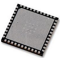
LTC3675EUFF#PBF Linear Technology, LTC3675EUFF#PBF Datasheet - Page 24

LTC3675EUFF#PBF
Manufacturer Part Number
LTC3675EUFF#PBF
Description
IC, PMIC, 1A, QFN-44
Manufacturer
Linear Technology
Datasheet
1.LTC3675EUFFPBF.pdf
(36 pages)
Specifications of LTC3675EUFF#PBF
Supply Voltage
5.5V
No. Of Step-down Dc - Dc Converters
4
No. Of Ldo Regulators
1
Digital Ic Case Style
QFN
No. Of Pins
44
No. Of Regulated Outputs
7
Operating Temperature Range
-40°C To +125°C
Rohs Compliant
Yes
Lead Free Status / RoHS Status
Lead free / RoHS Compliant
Available stocks
Company
Part Number
Manufacturer
Quantity
Price
LTC3675
OPERATION
data from the selected register. A STOP command is not
required for the bus read operation.
Immediately after writing data to a register, the contents of
that register may be read back if the bus master issues a
START condition followed by the LTC3675 read address.
ERROR CONDITION REPORTING VIA
RSTB AND IRQB PINS
Error conditions are reported back via the IRQB and RSTB
pins. After an error condition is detected, status data can
be read back to a microprocessor via I
exact nature of the error condition.
Figure 4 is a simplifi ed schematic showing the signal path
for reporting errors via the RSTB and IRQB pins.
All the switching regulators and the LED driver have an
internal power good (PGOOD) signal. When the regulated
output voltage of an enabled switcher rises above 93.5%
of its programmed value, the PGOOD signal will transition
high. When the regulated output voltage falls below 92.5%
of its programmed value, the PGOOD signal is pulled low.
24
92.5% OF PROGRAMMED V
REGULATOR
IRQB MASK REGISTER
OUT
+
–
V
PGOOD
COMPARATOR
OUT
Figure 4. Simplifi ed Schematic Showing RSTB and IRQB Signal Path
RSTB MASK REGISTER
2
C to determine the
AND1
AND2
OTHER UNMASKED
OTHER UNMASKED
PGOOD OUTPUTS
PGOOD OUTPUTS
UNMASKED
UNMASKED
ERRORS
ERROR
If that PGOOD is not masked and stays low for greater than
50μs, then it pulls the RSTB and IRQB pins low, indicating
to a microprocessor that an error condition has occurred.
The 50μs fi lter time prevents the pins from being pulled
low due to a transient.
The LED driver has a PGOOD signal (PGOOD[7]) that
is used to indicate output voltage status only when it is
confi gured as a high voltage boost regulator. In all other
operating modes, PGOOD[7] is disabled.
An error condition that pulls the RSTB pin low is not
latched. When the error condition goes away, the RSTB
pin is released and is pulled high if no other error condi-
tion exists.
In addition to the PGOOD signals of the regulators, the
IRQB pin also indicates the status of the overtemperature
and undervoltage fl ags. The undervoltage and overtem-
perature faults cannot be masked. A fault that causes
the IRQB pin to be pulled low is latched. When the fault
condition is cleared, the IRQB pin is still maintained in its
low state. The user needs to clear the interrupt by using
a CLRINT command.
CLRINT
V
IN
EXTERNAL PULL-UP RESISTOR
SET
CLR
RSTB
REAL TIME STATUS REGISTER
LATCHED STATUS REGISTER
V
IN
EXTERNAL PULL-UP RESISTOR
IRQB
3675 F04
3675f


