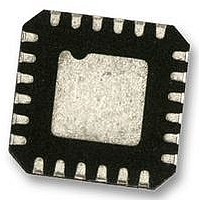
ADP5587ACPZ-R7 Analog Devices Inc, ADP5587ACPZ-R7 Datasheet - Page 12

ADP5587ACPZ-R7
Manufacturer Part Number
ADP5587ACPZ-R7
Description
IC, I/O EXPANDER, 400KHZ, LFCSP-24
Manufacturer
Analog Devices Inc
Type
I²C Port Expanderr
Datasheet
1.ADP5587ACPZ-R7.pdf
(24 pages)
Specifications of ADP5587ACPZ-R7
Bus Frequency
400kHz
Ic Interface Type
I2C
No. Of I/o's
18
Supply Voltage Range
1.7V To 3.6V
Digital Ic Case Style
LFCSP
No. Of Pins
24
Msl
MSL 3 - 168 Hours
Supply Voltage Max
3.6V
Applications
Cell Phone
Mounting Type
Surface Mount
Package / Case
24-LFCSP
Interface Type
I2C
Lead Free Status / RoHS Status
Lead free / RoHS Compliant
Other names
ADP5587ACPZ-R7TR
ADP5587
GENERAL-PURPOSE INPUTS AND OUTPUTS
The ADP5587 supports up to 18 programmable GPIOs that can
be configured to address a variety of uses. Figure 14 shows the
makeup of a typical GPIO block where GPIOx represents any of
the 18 I/O lines.
General-Purpose Inputs (GPI)
The ADP5587 allows the user to configure all or some of its
GPIOs as general-purpose inputs (GPIs). After the GPIOs are
configured as GPIs, the user can choose to also turn on pull-up
resistors and interrupt generation capability, thus reducing the
amount of software monitoring and processor interaction and
saving power.
The programmed level of the GPI interrupt determines the
active level of the GPI pin. For example, if a GPI interrupt level
is programmed as high, a high on that pin is considered active
and meets the interrupt requirement. If the interrupt is pro-
grammed as low, a low on that pin is considered active and
meets the interrupt requirement.
GPI data status and interrupt status are reflected in the GPIO
interrupt status and data status registers (Register 0x11 through
Register 0x16). Caution is necessary during software imple-
mentation because an interrupt may be set immediately after
the registers are set. To prevent this, the correct logic levels
must be present at the GPIs, and the GPIO interrupt level must
be set before GPIO interrupt enable or GPI event FIFO enable
registers are set. Figure 15 shows the interrupt generation
scheme, where Dx represents any one of the 18 GPIOs.
NOTES:
1. Dx_IN STANDS FOR ANY OF THE 18 GPIOs CONFIGURED AS GPIs.
2. Dx_OUT STANDS FOR ANY OF THE 18 GPIOs CONFIGURED AS GPOs.
3. Dx_IN_DBNC STANDS FOR GPI DEBOUNCE.
4. Dx_DIR STANDS FOR GPIO DIRECTION.
5. Dx_PULL STANDS FOR GPIO PULL-UP.
Dx_IN_DBNC
Dx_IN
Dx_OUT
Dx_DIR
DEBOUNCE
V
CC
Dx_PULL
Figure 14. Typical GPIO Block
V
CC
GPIOx
Rev. B | Page 12 of 24
GPI Events
A column or row configured as a GPI can be programmed to be
part of the key event table and is, therefore, also capable of
generating a key event interrupt. A key event interrupt caused
by a GPI follows the same process flow as a key event interrupt
caused by a key press or key release. GPIs configured as part of
the key event table allow single key switches and other GPI
interrupts to be monitored. As part of the event table, GPIs are
represented by a decimal value of 97 (0x61 hexadecimal or
1100001 binary) through a decimal value of 114 (0x72
hexadecimal or 1110010 binary). See Table 12 and Table 13 for
GPI event number assignments for rows and columns,
respectively.
Table 12. GPI Event Number Assignments for Rows
R0
97
Table 13. GPI Event Number Assignments for Columns
C0
105
For a GPI that is set as active high and is enabled in the key
event table, the state machine adds an event to the event count
and event tables whenever that GPI goes high. If the GPI is set
to active low, a transition from high to low is considered a press
and is also added to the event count and event table. After the
interrupt state is met, the state machine internally sets an
interrupt for the opposite state programmed in the register to
prevent polling for the released state, thereby saving current.
After the released state is achieved, it is added to the event table.
The press and release are still indicated by Bit 7 in the event
register (Register 0x04 through Register 0x0D). The GPI events
can also be used as unlocked sequences.
When the GPI_EM_REGx bit in Register 0x20 through Register
0x22 is set, GPI events are not tracked when the keypad is locked.
The GPIEM_CFG bit (Register 0x01, Bit 6) must be cleared for
the GPI events to be tracked in the event counter and event
table when the keypad is locked.
NOTES:
1. Dx_IN STANDS FOR ANY OF THE 18 GPIOs CONFIGURED AS GPIs.
2. Dx_ILVL STANDS FOR GPIO INTERRUPT LEVEL.
3. Dx_IN_IEN STANDS FOR GPI INTERRUPT ENABLE.
4. Dx_IN_STAT STANDS FOR GPI INTERRUPT STATUS.
5. GPI_INT STANDS FOR GPI INTERRUPT.
Dx_IN_IEN
REG. 0x23
THROUGH
REG. 0x25
REG. 0x26
THROUGH
REG. 0x28
REG. 0x01
Dx_ILVL
Dx_IN
C1
106
R1
98
C2
107
INTERRUPT
CONDITION
DECODE
Figure 15. GPIO Interrupt Generation
R2
99
C3
108
R3
100
AND
C4
109
READ TWICE
Dx_IN_ISTAT
THROUGH
TO CLEAR
REG. 0x11
REG. 0x13
R4
101
C5
110
C6
111
R5
102
REG. 0x02
TO CLEAR
WRITE 1
GPI_INT
C7
112
R6
103
C8
113
INT
DRIVE
R7
104
C9
114


