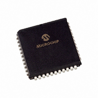
PIC16F874-20/L Microchip Technology, PIC16F874-20/L Datasheet - Page 453

PIC16F874-20/L
Manufacturer Part Number
PIC16F874-20/L
Description
IC MCU FLASH 4KX14 EE 44PLCC
Manufacturer
Microchip Technology
Series
PIC® 16Fr
Datasheets
1.PIC16F616T-ISL.pdf
(8 pages)
2.PIC16F688T-ISL.pdf
(688 pages)
3.PIC16F873-04SO.pdf
(218 pages)
4.PIC16F873-04SO.pdf
(5 pages)
5.PIC16F873-04SO.pdf
(5 pages)
Specifications of PIC16F874-20/L
Core Size
8-Bit
Program Memory Size
7KB (4K x 14)
Core Processor
PIC
Speed
20MHz
Connectivity
I²C, SPI, UART/USART
Peripherals
Brown-out Detect/Reset, POR, PWM, WDT
Number Of I /o
33
Program Memory Type
FLASH
Eeprom Size
128 x 8
Ram Size
192 x 8
Voltage - Supply (vcc/vdd)
4 V ~ 5.5 V
Data Converters
A/D 8x10b
Oscillator Type
External
Operating Temperature
0°C ~ 70°C
Package / Case
44-PLCC
Controller Family/series
PIC16F
No. Of I/o's
33
Eeprom Memory Size
128Byte
Ram Memory Size
192Byte
Cpu Speed
20MHz
No. Of Timers
3
Processor Series
PIC16F
Core
PIC
Data Bus Width
8 bit
Data Ram Size
192 B
Interface Type
MSSP, PSP, USART
Maximum Clock Frequency
20 MHz
Number Of Programmable I/os
33
Number Of Timers
3
Operating Supply Voltage
2 V to 5.5 V
Maximum Operating Temperature
+ 70 C
Mounting Style
SMD/SMT
3rd Party Development Tools
52715-96, 52716-328, 52717-734
Development Tools By Supplier
PG164130, DV164035, DV244005, DV164005, PG164120, ICE2000, DM163022, DV164120
Minimum Operating Temperature
0 C
On-chip Adc
10 bit, 8 Channel
Lead Free Status / RoHS Status
Lead free / RoHS Compliant
For Use With
AC164309 - MODULE SKT FOR PM3 44PLCC444-1001 - DEMO BOARD FOR PICMICRO MCUDVA16XL441 - ADAPTER DEVICE ICE 44PLCC309-1040 - ADAPTER 44-PLCC ZIF TO 40-DIP309-1039 - ADAPTER 44-PLCC TO 40-DIPDV007003 - PROGRAMMER UNIVERSAL PROMATE II
Lead Free Status / Rohs Status
Details
Available stocks
Company
Part Number
Manufacturer
Quantity
Price
Company:
Part Number:
PIC16F874-20/L
Manufacturer:
Microchip Technology
Quantity:
10 000
- PIC16F616T-ISL PDF datasheet
- PIC16F688T-ISL PDF datasheet #2
- PIC16F873-04SO PDF datasheet #3
- PIC16F873-04SO PDF datasheet #4
- PIC16F873-04SO PDF datasheet #5
- Current page: 453 of 688
- Download datasheet (3Mb)
Resolution
.
Slope A/D
1997 Microchip Technology Inc.
(Bits)
16
14
12
10
Conversion
Time (ms)
16.384
4.096
1.024
0.256
The selection of the external capacitor is determined by the desired characteristics of the appli-
cation. These include
• Input Voltage Range (widest range of all input channels)
• Conversion Time
• Programmable Current Source Output Values
The selection of these values should be done to minimize the time between a comparator trip
(ADCIF bit is set) to the ADTMR overflow (OVFIF is set). This ensures that the entire range of
the ADTMR is used for the A/D conversion process.
The equation for selecting the ramp capacitor value is:
Table 24-2
time, and full scale voltage measurement.
This capacitor on the CDAC pin should have a low voltage-coefficient as found in teflon, polypro-
pylene, or polystyrene capacitors, for optimum results. This external capacitor must be dis-
charged at the beginning of each conversion cycle by setting the ADRST bit (ADCON0<1>). The
time for the ADRST bit to be set depends on the characteristics of the external capacitor for a
complete discharge.
Table 24-2: External Capacitor Selection (@ 4 MHz)
Capacitor = (conversion time in seconds) X
(Volts)
Scale
Full
3.5
2.0
1.5
3.5
2.0
1.5
3.5
2.0
1.5
3.5
2.0
1.5
provides example capacitor values for the desired Slope A/D resolution, conversion
(current source output in amps) / (full scale in volts)
ADDAC3:ADDC0
Slope A/D Current Source Select
1100
1010
1011
1101
1011
1100
1101
1001
1010
1011
1010
1011
Section 24. Slope A/D
Typical Output
( amps)
24.75
29.25
24.75
29.25
20.25
24.75
24.75
22.5
22.5
22.5
27
27
Calculated
Capacitor
0.126 F
0.184 F
0.270 F
50.7 nF
73.7 nF
8.56 nF
10.4 nF
15.4 nF
1.81 nF
2.88 nF
4.22 nF
CDAC
34 nF
DS31024A-page 24-11
Nearest Standard
CDAC Capacitor
0.12 F
0.18 F
0.27 F
8.2 nF
1.8 nF
2.7 nF
3.9 nF
Value
33 nF
47 nF
68 nF
10 nF
15 nF
24
Related parts for PIC16F874-20/L
Image
Part Number
Description
Manufacturer
Datasheet
Request
R

Part Number:
Description:
IC MCU FLASH 4KX14 EE 40DIP
Manufacturer:
Microchip Technology
Datasheet:

Part Number:
Description:
IC MCU FLASH 4KX14 EE 40DIP
Manufacturer:
Microchip Technology
Datasheet:

Part Number:
Description:
IC MCU FLASH 4KX14 EE 44PLCC
Manufacturer:
Microchip Technology
Datasheet:

Part Number:
Description:
IC MCU FLASH 4KX14 EE 44TQFP
Manufacturer:
Microchip Technology
Datasheet:

Part Number:
Description:
IC MCU FLASH 4KX14 EE 40DIP
Manufacturer:
Microchip Technology
Datasheet:

Part Number:
Description:
IC,MICROCONTROLLER,8-BIT,PIC CPU,CMOS,QFP,44PIN,PLASTIC
Manufacturer:
Microchip Technology
Datasheet:

Part Number:
Description:
IC MCU FLASH 4KX14 EE 44PLCC
Manufacturer:
Microchip Technology
Datasheet:

Part Number:
Description:
IC MCU FLASH 4KX14 EE 44TQFP
Manufacturer:
Microchip Technology
Datasheet:

Part Number:
Description:
IC MCU FLASH 4KX14 EE 44MQFP
Manufacturer:
Microchip Technology
Datasheet:

Part Number:
Description:
IC MCU FLASH 4KX14 EE 44TQFP
Manufacturer:
Microchip Technology
Datasheet:

Part Number:
Description:
IC MCU FLASH 4KX14 EE 40DIP
Manufacturer:
Microchip Technology
Datasheet:

Part Number:
Description:
IC MCU FLASH 4KX14 EE 44-MQFP
Manufacturer:
Microchip Technology
Datasheet:

Part Number:
Description:
IC MCU FLASH 4KX14 EE 40DIP
Manufacturer:
Microchip Technology
Datasheet:

Part Number:
Description:
IC MCU FLASH 4KX14 EE 44PLCC
Manufacturer:
Microchip Technology
Datasheet:

Part Number:
Description:
IC MCU FLASH 4KX14 EE 44PLCC
Manufacturer:
Microchip Technology
Datasheet:


