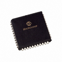
PIC16F874-20/L Microchip Technology, PIC16F874-20/L Datasheet - Page 428

PIC16F874-20/L
Manufacturer Part Number
PIC16F874-20/L
Description
IC MCU FLASH 4KX14 EE 44PLCC
Manufacturer
Microchip Technology
Series
PIC® 16Fr
Datasheets
1.PIC16F616T-ISL.pdf
(8 pages)
2.PIC16F688T-ISL.pdf
(688 pages)
3.PIC16F873-04SO.pdf
(218 pages)
4.PIC16F873-04SO.pdf
(5 pages)
5.PIC16F873-04SO.pdf
(5 pages)
Specifications of PIC16F874-20/L
Core Size
8-Bit
Program Memory Size
7KB (4K x 14)
Core Processor
PIC
Speed
20MHz
Connectivity
I²C, SPI, UART/USART
Peripherals
Brown-out Detect/Reset, POR, PWM, WDT
Number Of I /o
33
Program Memory Type
FLASH
Eeprom Size
128 x 8
Ram Size
192 x 8
Voltage - Supply (vcc/vdd)
4 V ~ 5.5 V
Data Converters
A/D 8x10b
Oscillator Type
External
Operating Temperature
0°C ~ 70°C
Package / Case
44-PLCC
Controller Family/series
PIC16F
No. Of I/o's
33
Eeprom Memory Size
128Byte
Ram Memory Size
192Byte
Cpu Speed
20MHz
No. Of Timers
3
Processor Series
PIC16F
Core
PIC
Data Bus Width
8 bit
Data Ram Size
192 B
Interface Type
MSSP, PSP, USART
Maximum Clock Frequency
20 MHz
Number Of Programmable I/os
33
Number Of Timers
3
Operating Supply Voltage
2 V to 5.5 V
Maximum Operating Temperature
+ 70 C
Mounting Style
SMD/SMT
3rd Party Development Tools
52715-96, 52716-328, 52717-734
Development Tools By Supplier
PG164130, DV164035, DV244005, DV164005, PG164120, ICE2000, DM163022, DV164120
Minimum Operating Temperature
0 C
On-chip Adc
10 bit, 8 Channel
Lead Free Status / RoHS Status
Lead free / RoHS Compliant
For Use With
AC164309 - MODULE SKT FOR PM3 44PLCC444-1001 - DEMO BOARD FOR PICMICRO MCUDVA16XL441 - ADAPTER DEVICE ICE 44PLCC309-1040 - ADAPTER 44-PLCC ZIF TO 40-DIP309-1039 - ADAPTER 44-PLCC TO 40-DIPDV007003 - PROGRAMMER UNIVERSAL PROMATE II
Lead Free Status / Rohs Status
Details
Available stocks
Company
Part Number
Manufacturer
Quantity
Price
Company:
Part Number:
PIC16F874-20/L
Manufacturer:
Microchip Technology
Quantity:
10 000
- PIC16F616T-ISL PDF datasheet
- PIC16F688T-ISL PDF datasheet #2
- PIC16F873-04SO PDF datasheet #3
- PIC16F873-04SO PDF datasheet #4
- PIC16F873-04SO PDF datasheet #5
- Current page: 428 of 688
- Download datasheet (3Mb)
PICmicro MID-RANGE MCU FAMILY
23.4
DS31023A-page 23-6
A/D Acquisition Requirements
For the A/D converter to meet its specified accuracy, the charge holding capacitor (C
be allowed to fully charge to the input channel voltage level. The analog input model is shown in
Figure
directly affect the time required to charge the capacitor C
ance varies over the device voltage (V
ance for analog sources is 10 k . As the impedance is decreased, the acquisition time may be
decreased. After the analog input channel is selected (changed) this acquisition must be done
before the conversion can be started.
To calculate the minimum acquisition time,
that 1/2 LSb error is used (1024 steps for the A/D). The 1/2 LSb error is the maximum error
allowed for the A/D to meet its specified resolution.
Equation 23-1:
Equation 23-2:
Example 23-1
This calculation is based on the following application system assumptions.
C
Rs
Conversion Error
V
Temperature
V
Example 23-1:
T
T
Temperature coefficient is only required for temperatures > 25 C.
T
T
T
DD
HOLD
HOLD
V
or
Tc
ACQ
ACQ
ACQ
C
ACQ
HOLD
=
=
23-3. The source impedance (R
=
=
=
=
Amplifier Settling Time +
Holding Capacitor Charging Time +
Temperature Coefficient
T
=
=
T
2 s + Tc + [(Temp - 25 C)(0.05 s/ C)]
-C
-120 pF (1 k + 7 k + 10 k ) ln(0.0004885)
-120 pF (18 k ) ln(0.0004885)
-2.16 s (-7.6241)
16.47 s
2 s + 16.47 s + [(50 C - 25 C)(0.05 s/ C)]
18.47 s + 1.25 s
19.72 s
shows the calculation of the minimum required acquisition time T
AMP
AMP
HOLD
Acquisition Time
A/D Minimum Charging Time
(V
-(120 pF)(1 k + R
Calculating the Minimum Required Acquisition Time (Case 1)
+ T
+ T
REF
(R
=
=
=
=
=
C
C
- (V
IC
+ T
+ T
+ R
Preliminary
120 pF
10 k
1/2 LSb
5V
50 C (system max.)
0V @ time = 0
REF
COFF
COFF
SS
/2048)) • (1 - e
+ R
Rss = 7 k
SS
S
DD
) ln(1/2047)
S
+ R
),
) and the internal sampling switch (R
Equation 23-1
Figure
S
) ln(1/2047)
(-Tc/C
23-3. The maximum recommended imped-
(see graph in
HOLD
HOLD
may be used. This equation assumes
(R
IC
. The sampling switch (R
+ R
SS
Figure
1997 Microchip Technology Inc.
+ R
S
))
)
23-3)
ACQ
SS
) impedance
.
HOLD
SS
) imped-
) must
Related parts for PIC16F874-20/L
Image
Part Number
Description
Manufacturer
Datasheet
Request
R

Part Number:
Description:
IC MCU FLASH 4KX14 EE 40DIP
Manufacturer:
Microchip Technology
Datasheet:

Part Number:
Description:
IC MCU FLASH 4KX14 EE 40DIP
Manufacturer:
Microchip Technology
Datasheet:

Part Number:
Description:
IC MCU FLASH 4KX14 EE 44PLCC
Manufacturer:
Microchip Technology
Datasheet:

Part Number:
Description:
IC MCU FLASH 4KX14 EE 44TQFP
Manufacturer:
Microchip Technology
Datasheet:

Part Number:
Description:
IC MCU FLASH 4KX14 EE 40DIP
Manufacturer:
Microchip Technology
Datasheet:

Part Number:
Description:
IC,MICROCONTROLLER,8-BIT,PIC CPU,CMOS,QFP,44PIN,PLASTIC
Manufacturer:
Microchip Technology
Datasheet:

Part Number:
Description:
IC MCU FLASH 4KX14 EE 44PLCC
Manufacturer:
Microchip Technology
Datasheet:

Part Number:
Description:
IC MCU FLASH 4KX14 EE 44TQFP
Manufacturer:
Microchip Technology
Datasheet:

Part Number:
Description:
IC MCU FLASH 4KX14 EE 44MQFP
Manufacturer:
Microchip Technology
Datasheet:

Part Number:
Description:
IC MCU FLASH 4KX14 EE 44TQFP
Manufacturer:
Microchip Technology
Datasheet:

Part Number:
Description:
IC MCU FLASH 4KX14 EE 40DIP
Manufacturer:
Microchip Technology
Datasheet:

Part Number:
Description:
IC MCU FLASH 4KX14 EE 44-MQFP
Manufacturer:
Microchip Technology
Datasheet:

Part Number:
Description:
IC MCU FLASH 4KX14 EE 40DIP
Manufacturer:
Microchip Technology
Datasheet:

Part Number:
Description:
IC MCU FLASH 4KX14 EE 44PLCC
Manufacturer:
Microchip Technology
Datasheet:

Part Number:
Description:
IC MCU FLASH 4KX14 EE 44PLCC
Manufacturer:
Microchip Technology
Datasheet:


