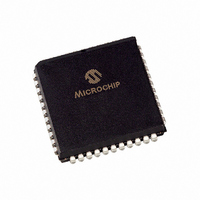
PIC16F874-20/L Microchip Technology, PIC16F874-20/L Datasheet - Page 310

PIC16F874-20/L
Manufacturer Part Number
PIC16F874-20/L
Description
IC MCU FLASH 4KX14 EE 44PLCC
Manufacturer
Microchip Technology
Series
PIC® 16Fr
Datasheets
1.PIC16F616T-ISL.pdf
(8 pages)
2.PIC16F688T-ISL.pdf
(688 pages)
3.PIC16F873-04SO.pdf
(218 pages)
4.PIC16F873-04SO.pdf
(5 pages)
5.PIC16F873-04SO.pdf
(5 pages)
Specifications of PIC16F874-20/L
Core Size
8-Bit
Program Memory Size
7KB (4K x 14)
Core Processor
PIC
Speed
20MHz
Connectivity
I²C, SPI, UART/USART
Peripherals
Brown-out Detect/Reset, POR, PWM, WDT
Number Of I /o
33
Program Memory Type
FLASH
Eeprom Size
128 x 8
Ram Size
192 x 8
Voltage - Supply (vcc/vdd)
4 V ~ 5.5 V
Data Converters
A/D 8x10b
Oscillator Type
External
Operating Temperature
0°C ~ 70°C
Package / Case
44-PLCC
Controller Family/series
PIC16F
No. Of I/o's
33
Eeprom Memory Size
128Byte
Ram Memory Size
192Byte
Cpu Speed
20MHz
No. Of Timers
3
Processor Series
PIC16F
Core
PIC
Data Bus Width
8 bit
Data Ram Size
192 B
Interface Type
MSSP, PSP, USART
Maximum Clock Frequency
20 MHz
Number Of Programmable I/os
33
Number Of Timers
3
Operating Supply Voltage
2 V to 5.5 V
Maximum Operating Temperature
+ 70 C
Mounting Style
SMD/SMT
3rd Party Development Tools
52715-96, 52716-328, 52717-734
Development Tools By Supplier
PG164130, DV164035, DV244005, DV164005, PG164120, ICE2000, DM163022, DV164120
Minimum Operating Temperature
0 C
On-chip Adc
10 bit, 8 Channel
Lead Free Status / RoHS Status
Lead free / RoHS Compliant
For Use With
AC164309 - MODULE SKT FOR PM3 44PLCC444-1001 - DEMO BOARD FOR PICMICRO MCUDVA16XL441 - ADAPTER DEVICE ICE 44PLCC309-1040 - ADAPTER 44-PLCC ZIF TO 40-DIP309-1039 - ADAPTER 44-PLCC TO 40-DIPDV007003 - PROGRAMMER UNIVERSAL PROMATE II
Lead Free Status / Rohs Status
Details
Available stocks
Company
Part Number
Manufacturer
Quantity
Price
Company:
Part Number:
PIC16F874-20/L
Manufacturer:
Microchip Technology
Quantity:
10 000
- PIC16F616T-ISL PDF datasheet
- PIC16F688T-ISL PDF datasheet #2
- PIC16F873-04SO PDF datasheet #3
- PIC16F873-04SO PDF datasheet #4
- PIC16F873-04SO PDF datasheet #5
- Current page: 310 of 688
- Download datasheet (3Mb)
PICmicro MID-RANGE MCU FAMILY
17.4.10
DS31017A-page 17-34
I
2
C Master Mode Repeated Start Condition Timing
A Repeated Start condition occurs when the RSEN bit (SSPCON2<1>) is programmed high and
the I
When the SCL pin is sampled low, the baud rate generator is loaded with the contents of
SSPADD<5:0>, and begins counting. The SDA pin is released (brought high) for one baud rate
generator count (T
SCL pin will be de-asserted (brought high). When SCL is sampled high the baud rate generator
is re-loaded with the contents of SSPADD<6:0> and begins counting. SDA and SCL must be
sampled high for one T
for one T
cally cleared, and the baud rate generator is not reloaded, leaving the SDA pin held low. As soon
as a start condition is detected on the SDA and SCL pins, the S bit (SSPSTAT<3>) will be set.
The SSPIF bit will not be set until the baud rate generator has timed-out.
Immediately following the SSPIF bit getting set, the user may write the SSPBUF with the 7-bit
address in 7-bit mode, or the default first address in 10-bit mode. After the first eight bits are
transmitted and an ACK is received, the user may then transmit an additional eight bits of
address (10-bit mode) or eight bits of data (7-bit mode).
Note 1: If RSEN is programmed while any other event is in progress, it will not take effect.
Note 2: A bus collision during the Repeated Start condition occurs if:
2
C logic module is in the idle state. When the RSEN bit is set, the SCL pin is asserted low.
BRG
• SDA is sampled low when SCL goes from low to high.
• SCL goes low before SDA is asserted low. This may indicates that another
while SCL is high. Following this, the RSEN bit (SSPCON2<1>) will be automati-
master is attempting to transmit a data ‘1’.
BRG
). When the baud rate generator times out, if SDA is sampled high, the
BRG
. This action is then followed by assertion of the SDA pin (SDA = 0)
Preliminary
1997 Microchip Technology Inc.
Related parts for PIC16F874-20/L
Image
Part Number
Description
Manufacturer
Datasheet
Request
R

Part Number:
Description:
IC MCU FLASH 4KX14 EE 40DIP
Manufacturer:
Microchip Technology
Datasheet:

Part Number:
Description:
IC MCU FLASH 4KX14 EE 40DIP
Manufacturer:
Microchip Technology
Datasheet:

Part Number:
Description:
IC MCU FLASH 4KX14 EE 44PLCC
Manufacturer:
Microchip Technology
Datasheet:

Part Number:
Description:
IC MCU FLASH 4KX14 EE 44TQFP
Manufacturer:
Microchip Technology
Datasheet:

Part Number:
Description:
IC MCU FLASH 4KX14 EE 40DIP
Manufacturer:
Microchip Technology
Datasheet:

Part Number:
Description:
IC,MICROCONTROLLER,8-BIT,PIC CPU,CMOS,QFP,44PIN,PLASTIC
Manufacturer:
Microchip Technology
Datasheet:

Part Number:
Description:
IC MCU FLASH 4KX14 EE 44PLCC
Manufacturer:
Microchip Technology
Datasheet:

Part Number:
Description:
IC MCU FLASH 4KX14 EE 44TQFP
Manufacturer:
Microchip Technology
Datasheet:

Part Number:
Description:
IC MCU FLASH 4KX14 EE 44MQFP
Manufacturer:
Microchip Technology
Datasheet:

Part Number:
Description:
IC MCU FLASH 4KX14 EE 44TQFP
Manufacturer:
Microchip Technology
Datasheet:

Part Number:
Description:
IC MCU FLASH 4KX14 EE 40DIP
Manufacturer:
Microchip Technology
Datasheet:

Part Number:
Description:
IC MCU FLASH 4KX14 EE 44-MQFP
Manufacturer:
Microchip Technology
Datasheet:

Part Number:
Description:
IC MCU FLASH 4KX14 EE 40DIP
Manufacturer:
Microchip Technology
Datasheet:

Part Number:
Description:
IC MCU FLASH 4KX14 EE 44PLCC
Manufacturer:
Microchip Technology
Datasheet:

Part Number:
Description:
IC MCU FLASH 4KX14 EE 44PLCC
Manufacturer:
Microchip Technology
Datasheet:


