DC-2R5E224U-E Elna America, DC-2R5E224U-E Datasheet - Page 27
DC-2R5E224U-E
Manufacturer Part Number
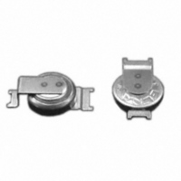
DC-2R5E224U-E
Description
CAP DOUBLE LAYER .22F 2.5V COIN
Manufacturer
Elna America
Series
DCr
Specifications of DC-2R5E224U-E
Capacitance
220mF
Voltage - Rated
2.5V
Tolerance
-20%, +80%
Esr (equivalent Series Resistance)
100.00 Ohm
Lifetime @ Temp.
1000 Hrs @ 70°C
Mounting Type
Surface Mount
Package / Case
Surface Mount - Coin Style
Lead Spacing
0.079" (2.00mm)
Height
0.295" (7.50mm)
Size / Dimension
0.268" Dia (6.80mm)
Operating Temperature
-25°C ~ 70°C
Lead Free Status / RoHS Status
Lead free / RoHS Compliant
Other names
604-1006


●
●
Specifications
* Note : If any doubt arises, measure the leakage current after following voltage application treatment.
Outline Drawing
●
●
●
NOTE
Design, Specifications are subject to change without notice.
Ask factory for technical specifications before purchase and/or use.
Tolerance at rated capacitance (%)
Damp heat, steady state
Tangent of loss angle (tanδ)
Characteristics of applied
(Applied ripple current)
Soldering conditions are described on page 11.
Land pattern size are described on page 12.
The taping specifications are described on page 13.
Super low E.S.R. and high ripple current are realized.
Guaranteed 105℃, 2000 hours.
Category temperature range (℃)
Characteristics at high
Leakage current (µA)
and low temperature
60℃, 90 to 95%RH
Endurance (105℃)
Chip Type
surge voltage
φD
Failure tare
6.3
10
Voltage application treatment : DC rated voltage are applied to the capacitors for 120 minutes at 105℃.
(humidity)
8
*Note
Item
5.7
6.7
7.7
L
®
L±0.3
10.4
6.6
8.4
A
GREEN
C : Rated capacitance (µF) ; V : Rated voltage (V)
Impedance ratio (max.)
The capacitors shall be subject to 1000 cycles each consisting of charge with the surge voltage specified at 15 to 35℃ for 30 seconds
through a protective resister (Rc=1kΩ) in 6 minutes per cycle. Surge voltage : 1.15 times of rated voltage
0.3MAX
CAP
10.4
6.6
8.4
B
Percentage of capacitance change
Percentage of capacitance change
Percentage of capacitance change
2.7
3.0
3.2
SMD
C
Tangent of the loss angle
Tangent of the loss angle
Tangent of the loss angle
Leakage current (µA)
Rated voltage (V)
0.5 to 0.8
0.5 to 0.8
0.7 to 1.1
Leakage current
Leakage current
Leakage current
E.S.R. change
E.S.R. change
E.S.R. change
A±0.2
Low
ESR
Test time
Test time
W
W
2000hours
105˚C
2.0
3.1
4.7
( ) : Reference size
P
Casing symbol
cleaning
solvent
0.5% per 1000 hours maximum (Confidence level 60% at 105℃)
Anti-
F60
G70
H80
Unit : mm
WITH CONDUCTIVE POLYMER SOLID ELECTROLYTE
Z−55℃/Z +20℃ : 1.50
PVH
Part numbering system (example : 4V150µF)
Less than 0.12
Series code
−55 to +105
ALUMINUM ELECTROLYTIC CAPACITORS
Performance
Less than 0.2 CV
PVH
±20
2.5 to 20
̶
2000 hours
The initial specified value or less
Within ±20% of initial value
150% or less of the initial specified value
200% or less of the initial specified value
500 hours
The initial specified value or less
Within ±20% of initial value
150% or less of the initial specified value
200% or less of the initial specified value
The initial specified value or less
Within ±20% of initial value
150% or less of the initial specified value
200% or less of the initial specified value
Rated voltage
symbol
4
V
Rated capacitance
151
symbol
tolerance symbol
Capacitance
CAT.No.2008/2009E ( 2008.10.1 )
M
Less than 0.5 CV
25
F60
Casing
symbol
PVH
Z
̶
(20℃,120Hz)
(20℃,120Hz)
(100kHz)
Taping
symbol
(20℃)
Related parts for DC-2R5E224U-E
Image
Part Number
Description
Manufacturer
Datasheet
Request
R

Part Number:
Description:
IC H-BRIDGE 7A DC MOTOR PDSO-20
Manufacturer:
Infineon Technologies
Datasheet:

Part Number:
Description:
DC 38..75Vi>15Vo 6.6A 99W
Manufacturer:
Power-One
Datasheet:

Part Number:
Description:
DC/DC Converters & Regulators 48W 24V 2A
Manufacturer:
POWER ONE

Part Number:
Description:
CONV DC-DC 50W 24VDC CASSETTE
Manufacturer:
POWER ONE
Datasheet:


Part Number:
Description:
CAP DOUBLE LAYER .10F 5.5V COIN
Manufacturer:
Elna America
Datasheet:

Part Number:
Description:
Supercapacitors V/MOUNT 5.5V 0.1F
Manufacturer:
Elna America
Datasheet:

Part Number:
Description:
CAP DOUBLE LAYER .07F 3.3V COIN
Manufacturer:
Elna America
Datasheet:

Part Number:
Description:
Vertical Chip Type Aluminum Electrolytic Capacitors
Manufacturer:
ELNA America, Inc.
Datasheet: