DC-2R5E224U-E Elna America, DC-2R5E224U-E Datasheet - Page 21
DC-2R5E224U-E
Manufacturer Part Number
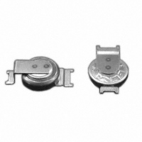
DC-2R5E224U-E
Description
CAP DOUBLE LAYER .22F 2.5V COIN
Manufacturer
Elna America
Series
DCr
Specifications of DC-2R5E224U-E
Capacitance
220mF
Voltage - Rated
2.5V
Tolerance
-20%, +80%
Esr (equivalent Series Resistance)
100.00 Ohm
Lifetime @ Temp.
1000 Hrs @ 70°C
Mounting Type
Surface Mount
Package / Case
Surface Mount - Coin Style
Lead Spacing
0.079" (2.00mm)
Height
0.295" (7.50mm)
Size / Dimension
0.268" Dia (6.80mm)
Operating Temperature
-25°C ~ 70°C
Lead Free Status / RoHS Status
Lead free / RoHS Compliant
Other names
604-1006


NOTE
Design, Specifications are subject to change without notice.
Ask factory for technical specifications before purchase and/or use.
11. The case of solid conductive polymer aluminum
electrolytic capacitors and the cathode terminal are
not insulated.
• The case and the cathode terminal are not insulated
12. Double-sided PCB’s
• When using capacitors on a double-sided PCB,
13. Regarding Connection of Solid Conductive
Polymer Aluminum Electrolytic Capacitors
14. Other Notes
1. Cautions for Mounting
2. Do not apply excessive pressure to the capaci-
tor or its terminals
• Before transportation of electronic equipment to
• When connecting more than one capacitor in
• Do not use capacitors on a circuit where rapid
• Electrical characteristics of capacitors vary by
• Do not reuse capacitors that have been assembled
• Before mounting, confirm the capacitor ratings
• Capacitors may generate transient recovery voltage.
• Before mounting, confirm the polarity of capacitor.
• Do not drop capacitors onto a floor nor use them.
• Do not mount deformed capacitors.
• Do not mount heating parts around capacitors and
• Be careful of the shock force that can be produced
(rated capacitance and rated voltage).
overseas, fumigation process may be subjected to
wooden
(compound) gas such as methyl bromide. Exercise
care that this halogen gas may corrode capacitors.
Also, be careful of epidemic preventive agent as
corrosive component such as halogen may be
contained.
as being connected through inconstant resistance.
exercise care that the wiring pattern does not touch
the area where the capacitors are mounted. Failure
to do so may cause a short to occur to the PCB
depending on the mounting conditions.
parallel, consider the current balance.
charge and discharge are repeated.
variations in temperature and frequency. Please
consider these variations when designing a circuit.
in a set and energized. Capacitors cannot be reused
except for those which have been measured on
electrical performance during periodic inspection.
In this case, discharge through a resistor of about
1 kΩ.
on the back of the PCB under or back of capacitors).
Cautions for Mounting
packing
®
WITH CONDUCTIVE POLYMER SOLID ELECTROLYTE
material
ALUMINUM ELECTROLYTIC CAPACITORS
with
a
halogen
3. Soldering
4. Handling after Soldering
• Do not tilt, fall, raise or twist capacitor body.
• Do not pick up or move PCB by holding a capacitor.
• Do not bump capacitors against objects. When
• Do not subject capacitors to excessive stress.
5. Cleaning after Soldering
• Recommended cleaning method
• Do not solder capacitor body by dipping into melted
• Soldering
• Flux should not adhere to the parts other than the
• When using a soldering iron, avoid excessive stress
• In reflow soldering, the reflow should be conducted
• Although leakage current may increase (from a few
• In case of a long-term use of equipment, control the
by absorbers, product checkers, and centering on
automatic inserters and installers.
solder.
temperature, terminal dipping time) should be within
the ranges specified in the catalog or the delivery
specification.
terminals.
to capacitor body.
once. Please be sure to consult with us if reflow
must be conducted twice.
µA to hundreds of µA) after soldering, it can be
reduced through self-repair by applying voltage. It is
advised to operate the set properly after treating
with the recommended voltage.
soldering characteristics so that capacitors and PCB
do not fail to connect to avoid abnormal current
passage by a failure of soldering to mount.
stacking PCB’s, make sure that capacitors do not
touch the PCB’s or other components.
①cleaning solutions:
②Cleaning conditions:
TECHNICAL NOTE
(a) CLEANTHROUGH 710M, 750H, 750L
(b) PINEALPHA ST-100S
(c) Techno Care FRW-4~17
(d) Isopropyl alcohol (2-propanol)
(a) The temperature of cleaning solution shall be
(b) Use immersion or ultrasonic waves within two
(c) After cleaning, capacitors and PCB’s shall
(d) After cleaning, do not keep capacitors in
less than 60°C.
minutes.
thoroughly be rinsed and dried with hot blast
for more than 10 minutes. The temperature of
such breeze should be less than the upper
category temperature.
cleaning solution atmosphere or airtight
containers.
conditions
CAT.No.2008/2009E ( 2008.10.1 )
(preheating,
soldering
Related parts for DC-2R5E224U-E
Image
Part Number
Description
Manufacturer
Datasheet
Request
R

Part Number:
Description:
IC H-BRIDGE 7A DC MOTOR PDSO-20
Manufacturer:
Infineon Technologies
Datasheet:

Part Number:
Description:
DC 38..75Vi>15Vo 6.6A 99W
Manufacturer:
Power-One
Datasheet:

Part Number:
Description:
DC/DC Converters & Regulators 48W 24V 2A
Manufacturer:
POWER ONE

Part Number:
Description:
CONV DC-DC 50W 24VDC CASSETTE
Manufacturer:
POWER ONE
Datasheet:


Part Number:
Description:
CAP DOUBLE LAYER .10F 5.5V COIN
Manufacturer:
Elna America
Datasheet:

Part Number:
Description:
Supercapacitors V/MOUNT 5.5V 0.1F
Manufacturer:
Elna America
Datasheet:

Part Number:
Description:
CAP DOUBLE LAYER .07F 3.3V COIN
Manufacturer:
Elna America
Datasheet:

Part Number:
Description:
Vertical Chip Type Aluminum Electrolytic Capacitors
Manufacturer:
ELNA America, Inc.
Datasheet: