DC-2R5E224U-E Elna America, DC-2R5E224U-E Datasheet - Page 115
DC-2R5E224U-E
Manufacturer Part Number
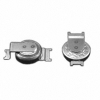
DC-2R5E224U-E
Description
CAP DOUBLE LAYER .22F 2.5V COIN
Manufacturer
Elna America
Series
DCr
Specifications of DC-2R5E224U-E
Capacitance
220mF
Voltage - Rated
2.5V
Tolerance
-20%, +80%
Esr (equivalent Series Resistance)
100.00 Ohm
Lifetime @ Temp.
1000 Hrs @ 70°C
Mounting Type
Surface Mount
Package / Case
Surface Mount - Coin Style
Lead Spacing
0.079" (2.00mm)
Height
0.295" (7.50mm)
Size / Dimension
0.268" Dia (6.80mm)
Operating Temperature
-25°C ~ 70°C
Lead Free Status / RoHS Status
Lead free / RoHS Compliant
Other names
604-1006


TECHNICAL NOTE
Circuit for connecting two capacitors (C1, C2) in series
and equivalent circuit can be illustrated as below figure.
Formula to calculate a balance resistance R
figure is shown as follows.
①
②
③
CAT.No.2008/2009E ( 2008.10.1 )
3 To calculate Balance when connecting in
3-1 Circuit layout
Following are the preconditions of the circuit.
3-2 Formulas to calculate [R
3-2-1 Following formula can be established from
balanced condition.
V
3-2-2 Following formula can be established from
preconditions.
3-2-3 Put formulas (1), (3) and (4’) in formula (2).
Accordingly, balance resistance R
following formula.
3-3 Calculation Example.
Calculate the value of the balance resistance in the
case of connecting two 400V 470µF ( LC standard
value : 1.88mA) capacitors in series.
C
C
1
series
V
V shall be a times V
R
1
2
2
2
V
V
shall be the rated voltage (=V
shall equal R
R
1
2
1
(2aV
2abV
2ab(R
R
1
≦ V
= V − V
=2aV
1
+
=
0
R
0
0
−V
1
(R
1
1.88(mA)
B
+R
0
400(V)
R
R
R
1
− V
+R
2
B
B
= V
B
)
2
≦2bR
B
1
) ≦ 2bR
×b.
2
B
R
R
2
)=V
1
1
0
×2. V=2aV
+ R
・ R
1
=213(kΩ)
R
R
R
1
2
1
2
(2a−1)
2
{b(R
1
+(1+b)R
B
B
+
(1−a)
B
=V
]
1
R
1
+R
B
2
•
b−1
0
0
B
R
R
).
)+bR
bR
bR
B
B
B
1
1
shall be the
+ R
・ R
(V
1
V
V
(a<1)
+R
1
(b<1) (1)
B
<V
1
2
B
B
of below
B
2
}
)
(4’)
(2)
(3)
(4)
(5)
V
ALUMINUM ELECTROLYTIC
CAPACITORS
Balance resistance R
4 Regarding Recovery Voltage
• After charging and then discharging the aluminum
electrolytic capacitor, and further causing short-circuit
to the terminals and leave them alone, the voltage
between the two terminals will rise again after some
interval. Voltage caused in such case is called recovery
voltage. Following is the process that causes this
phenomenon :
• When the voltage is impressed on a dielectric,
electrical transformation will be caused inside the
dielectric due to dielectric action, and electrification
will occur in positive-negative opposite to the voltage
impressed on the surface of the dielectric. This
phenomenon is called polarization action.
• After the voltage is impressed with this polarization
action, and if the terminals are discharged till the
terminal voltage reaches 0 and are left open for a while,
an electric potential will arise between the two terminals
and thus causes recovery voltage.
• Recovery voltage comes to a peak around 10 to 20
days after the two terminals are left open, and then
gradually declines. Recovery voltage has a tendency to
become bigger as the component (stand-alone base
type) becomes bigger.
• If the two terminals are short-circuited after the
recovery voltage is generated, a spark may scare the
workers working in the assembly line, and may put low-
voltage driven components (CPU, memory, etc.) in
danger of being destroyed. Measures to prevent this is
to discharge the accumulated electric charge with
resistor of about 100 to 1kΩ before using, or ship out
by making the terminals in short-circuit condition by
covering them with an aluminum foil at the production
stage. Please consult us for adequate procedures.
If a=0.8, 400(V)×2×0.8=640(V) as an impressed
If b=2, R
R
B
≦ 2×2×213(kΩ)
NOTE
Design, Specifications are subject to change without notice.
Ask factory for technical specifications before purchase and/or use.
voltage.
2
=b R
1
B
=426(kΩ), LC=0.94(mA).
will be.
(2×0.8)×2−1
(1−0.8)
=852(kΩ)
®
Related parts for DC-2R5E224U-E
Image
Part Number
Description
Manufacturer
Datasheet
Request
R

Part Number:
Description:
IC H-BRIDGE 7A DC MOTOR PDSO-20
Manufacturer:
Infineon Technologies
Datasheet:

Part Number:
Description:
DC 38..75Vi>15Vo 6.6A 99W
Manufacturer:
Power-One
Datasheet:

Part Number:
Description:
DC/DC Converters & Regulators 48W 24V 2A
Manufacturer:
POWER ONE

Part Number:
Description:
CONV DC-DC 50W 24VDC CASSETTE
Manufacturer:
POWER ONE
Datasheet:


Part Number:
Description:
CAP DOUBLE LAYER .10F 5.5V COIN
Manufacturer:
Elna America
Datasheet:

Part Number:
Description:
Supercapacitors V/MOUNT 5.5V 0.1F
Manufacturer:
Elna America
Datasheet:

Part Number:
Description:
CAP DOUBLE LAYER .07F 3.3V COIN
Manufacturer:
Elna America
Datasheet:

Part Number:
Description:
Vertical Chip Type Aluminum Electrolytic Capacitors
Manufacturer:
ELNA America, Inc.
Datasheet: