H5S-WB2 Omron, H5S-WB2 Datasheet - Page 12
H5S-WB2
Manufacturer Part Number
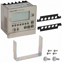
H5S-WB2
Description
TIMER DIGITAL WEEKLY 100-240VAC
Manufacturer
Omron
Series
H5Sr
Specifications of H5S-WB2
Supply Voltage
100 V to 240 V
Current Rating (max)
100 mA
Product
Digital Timer
Termination Style
Screw
No. Of Digits / Alpha
2
Meter Function
Counter
Supply Voltage Max
240VAC
Supply Voltage Min
100VAC
Lead Free Status / RoHS Status
Lead free / RoHS Compliant
Lead Free Status / RoHS Status
Lead free / RoHS Compliant, Lead free / RoHS Compliant
Other names
Z2504


Safety Precautions
Refer to Safety Precautions for All Timers.
■ Precautions for Safe Use
Observe all of the following precautions to maintain safety.
1. The Time Switch is not waterproof or oil resistant. Do not use it in
2. Use the following wire to wire the Time Switch: 600-V vinyl-
3. Do not connect more than two crimp terminals to each Time
4. None of the Time Switch components are user-replaceable,
■ Precautions for Correct Use
Be sure that the capacity of the power supply is large enough,
otherwise the Time Switch may not start due to the inrush current
(approx. 3 A) that flows for an instant when the power to the Time
Switch is turned ON.
ON Current and Ambient Temperature
(Reference Values)
If the ON current is too large, the upper limit to the ambient operating
temperature must be reduced as shown in the following diagram.
Mounting Dimensions
Flush Mounting
• Use a U-shaped mounting bracket to flush mount the unit.
Tighten terminal screws to the specified torque of approx.
0.8 N·m (maximum torque: 0.98 N·m). Loose screws may
occasionally cause fires or malfunction.
The Time Switch contains a lithium battery (explosion-
proof). Do not disassemble the Time Switch, deform the
Time Switch under pressure, heat the Time Switch to
above 100°C, or incinerate the Time Switch. Doing any of
these may result in fire or battery rupture.
locations subject to water or oil.
insulated wire (solid wire or twisted wire, copper), 14 to 24 AWG
Switch terminal.
including the battery.
60
55
50
40
0
Both circuits ON simultaneously
!CAUTION
5
10
ON Current (A AC or DC)
12
15
20
Surface Mounting
• Use a straight mounting bracket to surface mount the unit.
Track Mounting
• Hook the upper part on the rear surface to the upper edge of the
• To remove the Timer Switch from the DIN Track, pull
Wiring
Wiring From the Rear
• Perform wiring from the rear of
Wiring From the Front
• Perform wiring from the front of
Wiring Procedure
1. Loosen the screw on the left
2. Slide the upper part of the unit
3. After the terminals appear,
4. Return the upper part of the
Note: Screw tightening torque: 0.98 N·m max.
mounting track and press the unit down.
down on the yellow lever at the back of the Timer
Switch.
the unit when the unit is flush
mounted.
the unit when the unit is track
or surface mounted.
side of the front.
approx. 15 mm upward.
perform wiring.
unit to the original position and
tighten the screw.
(1)
(2)
M3.5
terminal screws
Yellow lever
H5L
12
Related parts for H5S-WB2
Image
Part Number
Description
Manufacturer
Datasheet
Request
R


Part Number:
Description:
TIMER WEEKLY DGTL PRESET DIN MNT
Manufacturer:
Omron
Datasheet:

Part Number:
Description:
TIMER YEARLY 4CIRCT 100-240V SMD
Manufacturer:
Omron
Datasheet:

Part Number:
Description:
TIMER DIGITAL WEEKLY 100-240VAC
Manufacturer:
Omron
Datasheet:

Part Number:
Description:
TIMER WEEKLY DGTL PRESET DIN MNT
Manufacturer:
Omron
Datasheet:

Part Number:
Description:
Timer, Weekly, Surface/Track mounting, 2 Circuit Outputs, 100to240vAC Supply Voltage
Manufacturer:
Omron Automation
Datasheet:
Part Number:
Description:
Timer, Yearly timer, 2-circuit (SPST-NO), 100-240VAC
Manufacturer:
Omron Automation
Datasheet:
Part Number:
Description:
G6S-2GLow Signal Relay
Manufacturer:
Omron Corporation
Datasheet:
Part Number:
Description:
Compact, Low-cost, SSR Switching 5 to 20 A
Manufacturer:
Omron Corporation
Datasheet: