HDJD-JD05 Avago Technologies US Inc., HDJD-JD05 Datasheet - Page 12
HDJD-JD05
Manufacturer Part Number
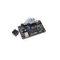
HDJD-JD05
Description
KIT DEV RGB COLOR SENSOR 20-QFN
Manufacturer
Avago Technologies US Inc.
Specifications of HDJD-JD05
Sensor Type
Light, Color Sensor
Sensing Range
RGB
Interface
2-Wire Serial
Voltage - Supply
2.5 V ~ 3.6 V
Embedded
No
Utilized Ic / Part
ADJD-S313-QR999
For Use With/related Products
ADJD-S313-QR999
Lead Free Status / RoHS Status
Not applicable / Not applicable


Ground Connection
AGND and DGND must both be set to 0V and
preferably star-connected to a central power source
as shown in the application diagram. A potential
difference between AGND and DGND may cause the
ESD diodes to turn on inadvertently.
Pin Information
12
Powering the Device
PIN
1
2
3
4
5
6
7
8
9
10
11
12
13
14
15
16
17
18
19
20
NAME
NC
NC
NC
NC
DGND
DGND
DVDD
NC
SCLSLV
SDASLV
NC
NC
SLEEP
NC
AGND
XRST
AGND
AGND
AGND
AVDD
No connect
No connect
No connect
No connect
Ground
Ground
Power
Ground
No connect
Input
Input
Input/Output
(tri-state high)
No connect
No connect
Input
Ground
Ground
Ground
Power
No connect
TYPE
Digital power pin.
No connect. Leave floating.
DESCRIPTION
No connect. Leave floating.
No connect. Leave floating.
No connect. Leave floating.
No connect. Leave floating.
No connect. Leave floating.
Global, asynchronous, active-low system reset. When asserted low, XRST
resets all registers. Minimum reset pulse low is 10 s and must be provided by
external circuitry.
SDASLV and SCLSLV are the serial interface communications pins. SDASLV is
should be tied to SDASLV because it goes tri-state to output logic 1.
No connect. Leave floating.
No connect. Leave floating.
circuits are powered down and the clock signal is gated away from the core
logic resulting in very low current consumption.
Tie to digital ground.
Tie to digital ground.
Tie to analog ground.
the bidirectional data pin and SCLSLV is the interface clock. A pull-up resistor
When SLEEP=1, the device goes into sleep mode. In sleep mode, all analog
Tie to analog ground.
Tie to analog ground.
Tie to analog ground.
Analog power pin.
Application Diagrams
SYSTEM
HOST
XRST
SDA
SCL
SYSTEM
HOST
DVDD
15
10
12
11
SLEEP
XRST
SDASLV
SCLSLV
Regulator
Voltage
AVDD
19
17, 18
8, 16,
AGND
Star-connected ground
5, 6
DGND
Regulator
Voltage
DVDD
7
Related parts for HDJD-JD05
Image
Part Number
Description
Manufacturer
Datasheet
Request
R

Part Number:
Description:
KIT DEV RGB COLOR SENSOR 16-QFN
Manufacturer:
Avago Technologies US Inc.
Datasheet:

Part Number:
Description:
KIT DEV RGB COLOR SENSOR 16-QFN
Manufacturer:
Avago Technologies US Inc.
Datasheet:

Part Number:
Description:
KIT DEV RGB DCS 2.2X2.2
Manufacturer:
Avago Technologies US Inc.
Datasheet:

Part Number:
Description:
Optical Sensor
Manufacturer:
Avago Technologies US Inc.
Datasheet:
Part Number:
Description:
RGB COLOR CONTROLLER AND SENSOR
Manufacturer:
Avago Technologies US Inc.
Part Number:
Description:
Photodiodes Color Controller
Manufacturer:
Avago Technologies US Inc.

Part Number:
Description:
Optical Sensors - Board Mount RGB Color Sensor
Manufacturer:
Avago Technologies US Inc.

Part Number:
Description:
Optical Sensors - Board Mount RGB Color Sensor
Manufacturer:
Avago Technologies US Inc.

Part Number:
Description:
Optical Sensor Development Tools RGB CONTROLLER Development Kit
Manufacturer:
Avago Technologies US Inc.

Part Number:
Description:
Optical Sensor Development Tools RGB CONTROLLER Development Kit
Manufacturer:
Avago Technologies US Inc.

Part Number:
Description:
OPTOCOUPLER GATE DRV 2A 16-SOIC
Manufacturer:
Avago Technologies US Inc.
Datasheet:
Part Number:
Description:
OPTOCOUPLER 2CH 2.5A 16-SOIC
Manufacturer:
Avago Technologies US Inc.
Datasheet:

Part Number:
Description:
OPTOCOUPLER GATE DRV 0.4A 16SOIC
Manufacturer:
Avago Technologies US Inc.
Datasheet:

Part Number:
Description:
OPTOCOUPLER 2.0A 250KHZ 8-DIP
Manufacturer:
Avago Technologies US Inc.
Datasheet:

Part Number:
Description:
OPTOCOUPLER 2.0A 250KHZ GW 8-SMD
Manufacturer:
Avago Technologies US Inc.
Datasheet: