ST7MDT20-DVP3 STMicroelectronics, ST7MDT20-DVP3 Datasheet - Page 26
ST7MDT20-DVP3
Manufacturer Part Number
ST7MDT20-DVP3
Description
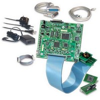
KIT EMULATOR FOR ST72321/324/521
Manufacturer
STMicroelectronics
Series
ST7-DVP3r
Type
Microcontrollerr
Datasheets
1.ST7MDT10-8DVP.pdf
(3 pages)
2.ST7MDT10-8DVP.pdf
(44 pages)
3.ST7MDT20-TEBDVP.pdf
(38 pages)
Specifications of ST7MDT20-DVP3
Contents
Main Emulation Board (MEB), Target Emulation Board (TEB), Cables, Power Supply and Documentation
For Use With/related Products
ST72321, ST72324, ST72521
Lead Free Status / RoHS Status
Lead free / RoHS Compliant
Other names
497-4874


In-circuit Communication Configuration
26/44
Isolation of ICCDATA and ICCCLK pins
As soon as the DVP3’s ICC connector is connected to the application board, the
ICCDATA and ICCCLK pins must not be used by other application devices, even if
an ICC session is not in progress. If the application uses these pins as inputs,
isolation such as a serial resistor must be implemented to prevent other application
devices from forcing a signal on either of these pins. The application board must
not drive current in excess of 1mA.
If the ICCDATA and ICCCLK pins are only used as outputs by the application, no
signal isolation is necessary.
For ST7 without an ICCSEL pin, during normal operation the ICCCLK pin must be
pulled-up internally or externally (10KΩ pull-up required in noisy environments).
This is to avoid entering ICC mode unintentionally during a reset.
Isolation of the RESET pin
During an ICC session, you must ensure that the emulator controls the ST7’s
RESET pin so that no external reset is generated by the application. This can lead
to a conflict if the application reset circuitry signal exceeds 5mA (push-pull output
or pull-up resistor <1K). To avoid such conflicts, a Shottky diode can be used to
isolate the application reset circuit.
ICCSEL/VPP pin
The application pull-down resistor must not be lower than 10kΩ.
ICCOSC pin
The ICCOSC pin of the ICC connector must be connected to the ST7’s OSC1 or
OSCIN pin if the clock is not provided by the application, or if the application clock
source is not programmed in the option byte. This connection allows you start
communication with your ST7 for in-circuit debugging using the Start with
External Clock (Ignore Option Bytes) option in STVD7, or for in-circuit
programming using the ICP OPT Disable mode in STVP7 or STVD7. When doing
so, your emulator provides a clock source to initiate communication with the ST7.
Your ST7-DVP3 emulator provides a clock source at a frequency of 8 MHz.
For ST7 devices with multi-oscillator capability, when the ICCOSC pin is
connected, the OSC2 pin should be grounded.
If your application provides a clock signal and you are certain that it is correctly
programmed in the ST7’s option byte, then it is not necessary to use the Start with
External Clock (Ignore Option Bytes) option when you start ICD in STVD7.
When starting ICP, you can use the ICP OPT Enable mode in STVP7 or STVD7.
ST7-DVP3 Emulator User Manual
Related parts for ST7MDT20-DVP3
Image
Part Number
Description
Manufacturer
Datasheet
Request
R

Part Number:
Description:
KIT CONNECTION ST7MDT20-DVP3
Manufacturer:
STMicroelectronics
Datasheet:
Part Number:
Description:
KIT CONNECTOR FOR STMDT20 44TQFP
Manufacturer:
STMicroelectronics
Datasheet:
Part Number:
Description:
BOARD TARGET EMULATION ST7-DVP
Manufacturer:
STMicroelectronics
Datasheet:
Part Number:
Description:
KIT CONNECTOR FOR STMDT20 80TQFP
Manufacturer:
STMicroelectronics
Datasheet:
Part Number:
Description:
KIT CONNECTOR FOR STMDT20 32TQFP
Manufacturer:
STMicroelectronics
Datasheet:
Part Number:
Description:
KIT CONNECTOR FOR STMDT20 64TQFP
Manufacturer:
STMicroelectronics
Datasheet:
Part Number:
Description:
BOARD EVALUATION/TRAINING/PROGRM
Manufacturer:
STMicroelectronics
Datasheet:
Part Number:
Description:
BOARD EVALUATION/TRAINING/PROGRM
Manufacturer:
STMicroelectronics
Datasheet:
Part Number:
Description:
BOARD PROGRAMMING SGL POS ST7
Manufacturer:
STMicroelectronics
Datasheet:
Part Number:
Description:
KIT DEVELOPMENT ST7
Manufacturer:
STMicroelectronics
Datasheet:

Part Number:
Description:
Low Cost, Real Time Emulator Series for ST7
Manufacturer:
STMICROELECTRONICS [STMicroelectronics]
Datasheet:
Part Number:
Description:
Full-featured, real time emulator series for ST7
Manufacturer:
STMICROELECTRONICS [STMicroelectronics]
Datasheet:
Part Number:
Description:
Programming board
Manufacturer:
STMICROELECTRONICS [STMicroelectronics]
Datasheet:
Part Number:
Description:
8-bit microcontroller with single voltage Flash memory, data EEPROM, ADC, timers, SPI
Manufacturer:
STMICROELECTRONICS [STMicroelectronics]
Datasheet:
Part Number:
Description:
In-Circuit Programmer
Manufacturer:
STMicroelectronics
Datasheet: