ST7MDT20-DVP3 STMicroelectronics, ST7MDT20-DVP3 Datasheet - Page 22
ST7MDT20-DVP3
Manufacturer Part Number
ST7MDT20-DVP3
Description
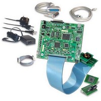
KIT EMULATOR FOR ST72321/324/521
Manufacturer
STMicroelectronics
Series
ST7-DVP3r
Type
Microcontrollerr
Datasheets
1.ST7MDT10-8DVP.pdf
(3 pages)
2.ST7MDT10-8DVP.pdf
(44 pages)
3.ST7MDT20-TEBDVP.pdf
(38 pages)
Specifications of ST7MDT20-DVP3
Contents
Main Emulation Board (MEB), Target Emulation Board (TEB), Cables, Power Supply and Documentation
For Use With/related Products
ST72321, ST72324, ST72521
Lead Free Status / RoHS Status
Lead free / RoHS Compliant
Other names
497-4874


Emulation Configuration
4.4
4.5
4.5.1
22/44
Changing configurations
Your ST7-DVP3 emulator is designed to connect to your application board either in
place of your ST7 via the probe (TEB, flat cables, adapters and socket), or the ICC
connection which is relayed to the ST7 on your application board. For more
information about the probe connection, refer to your ST7xxxx-DVP3 Probe User
Guide .
When using your emulator you must only use one connection at a time. If you
switch from one connection to another, follow the procedure outlined below.
Switching from probe connection to the ICC connection
1 Switch off the application board.
2 Disconnect the power to the ST7-DVP3 development board.
3 Unplug the probe from your application board.
4 Install the target MCU in its socket on the application board.
5 Plug one end of the ICC cable into the ICC connector on your ST7-DVP3
6 Reconnect the power supply for the ST7-DVP3 development board.
7 Switch on the power for the application board.
Emulator functional limitations and discrepancies
Limitations and discrepancies for specific MCUs or families of MCUs
Specific MCUs of families of MCUs may present certain limitations or
discrepancies. You will find information about these specific limitations in STVD7’s
Discrepancies window. For more information refer to the STVD7 User Manual .
development board, and plug the other end into the HE10 connector on your
application board.
ST7-DVP3 Emulator User Manual
Related parts for ST7MDT20-DVP3
Image
Part Number
Description
Manufacturer
Datasheet
Request
R

Part Number:
Description:
KIT CONNECTION ST7MDT20-DVP3
Manufacturer:
STMicroelectronics
Datasheet:
Part Number:
Description:
KIT CONNECTOR FOR STMDT20 44TQFP
Manufacturer:
STMicroelectronics
Datasheet:
Part Number:
Description:
BOARD TARGET EMULATION ST7-DVP
Manufacturer:
STMicroelectronics
Datasheet:
Part Number:
Description:
KIT CONNECTOR FOR STMDT20 80TQFP
Manufacturer:
STMicroelectronics
Datasheet:
Part Number:
Description:
KIT CONNECTOR FOR STMDT20 32TQFP
Manufacturer:
STMicroelectronics
Datasheet:
Part Number:
Description:
KIT CONNECTOR FOR STMDT20 64TQFP
Manufacturer:
STMicroelectronics
Datasheet:
Part Number:
Description:
BOARD EVALUATION/TRAINING/PROGRM
Manufacturer:
STMicroelectronics
Datasheet:
Part Number:
Description:
BOARD EVALUATION/TRAINING/PROGRM
Manufacturer:
STMicroelectronics
Datasheet:
Part Number:
Description:
BOARD PROGRAMMING SGL POS ST7
Manufacturer:
STMicroelectronics
Datasheet:
Part Number:
Description:
KIT DEVELOPMENT ST7
Manufacturer:
STMicroelectronics
Datasheet:

Part Number:
Description:
Low Cost, Real Time Emulator Series for ST7
Manufacturer:
STMICROELECTRONICS [STMicroelectronics]
Datasheet:
Part Number:
Description:
Full-featured, real time emulator series for ST7
Manufacturer:
STMICROELECTRONICS [STMicroelectronics]
Datasheet:
Part Number:
Description:
Programming board
Manufacturer:
STMICROELECTRONICS [STMicroelectronics]
Datasheet:
Part Number:
Description:
8-bit microcontroller with single voltage Flash memory, data EEPROM, ADC, timers, SPI
Manufacturer:
STMICROELECTRONICS [STMicroelectronics]
Datasheet:
Part Number:
Description:
In-Circuit Programmer
Manufacturer:
STMicroelectronics
Datasheet: