HS0005KCU01H Renesas Electronics America, HS0005KCU01H Datasheet - Page 13
HS0005KCU01H
Manufacturer Part Number
HS0005KCU01H
Description
ON CHIP DEBUG EMULATOR
Manufacturer
Renesas Electronics America
Type
In Circuit Debuggerr
Datasheets
1.HS0005KCU01H.pdf
(24 pages)
2.HS0005KCU01H.pdf
(45 pages)
3.HS0005KCU01H.pdf
(28 pages)
Specifications of HS0005KCU01H
Contents
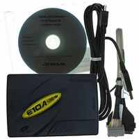
E10T-USB, Cable and CD-ROM
Lead Free Status / RoHS Status
Contains lead / RoHS non-compliant
For Use With/related Products
H8S, H8SX, SH-2, SH-2A, SH3, SH4, SH4A & SH-Mobile
Lead Free Status / RoHS Status
Not Compliant, Contains lead / RoHS non-compliant


Notes: 1. Input to or output from the user system.
Pin No.
1
2
3
4
5
6
7
8
9
11
10, 12,
and 13
14
Figure 1.2 Pin Assignments of the H-UDI Port Connector (14 Pins)
2. The slash (/) means that the signal is active-low.
3. The emulator monitors the GND signal of the user system and detects whether or not
4. The /ASEMD0 pin must be 0 when the emulator is connected and 1 when the emulator is
the user system is connected.
not connected, respectively.
(1) When the emulator is used: /ASEMD0 = 0
(2) When the emulator is not used: /ASEMD0 = 1
To allow the /ASEMD0 pin to be GND by connecting the user system interface cable,
connect pin 22 directly to the /ASEMD0 pin. Do not ground the pin.
Signal
GND
TCK
/TRST
TDO
/ASEBRKAK
TMS
TDI
/RESETP
/CA
(GND)
UVCC
GND
Pin 8
Pin 1
Pin 1 mark
Pin 1 mark
*2
*2
*2
*2
*4
*3
(2.54)
Input/
Output*
6 x 2.54 = 15.24
Input
Input
Output
Output
Input
Input
Output
Output
Output
Output
H-UDI port connector (top view)
25.0
23.0
1
User reset
Note
0.45
H-UDI port connector
(top view)
Pin 14
Pin 7
Unit: mm
5
Related parts for HS0005KCU01H
Image
Part Number
Description
Manufacturer
Datasheet
Request
R

Part Number:
Description:
KIT STARTER FOR M16C/29
Manufacturer:
Renesas Electronics America
Datasheet:

Part Number:
Description:
KIT STARTER FOR R8C/2D
Manufacturer:
Renesas Electronics America
Datasheet:

Part Number:
Description:
R0K33062P STARTER KIT
Manufacturer:
Renesas Electronics America
Datasheet:

Part Number:
Description:
KIT STARTER FOR R8C/23 E8A
Manufacturer:
Renesas Electronics America
Datasheet:

Part Number:
Description:
KIT STARTER FOR R8C/25
Manufacturer:
Renesas Electronics America
Datasheet:

Part Number:
Description:
KIT STARTER H8S2456 SHARPE DSPLY
Manufacturer:
Renesas Electronics America
Datasheet:

Part Number:
Description:
KIT STARTER FOR R8C38C
Manufacturer:
Renesas Electronics America
Datasheet:

Part Number:
Description:
KIT STARTER FOR R8C35C
Manufacturer:
Renesas Electronics America
Datasheet:

Part Number:
Description:
KIT STARTER FOR R8CL3AC+LCD APPS
Manufacturer:
Renesas Electronics America
Datasheet:
Part Number:
Description:
KIT STARTER FOR RX610
Manufacturer:
Renesas Electronics America
Datasheet:

Part Number:
Description:
KIT STARTER FOR R32C/118
Manufacturer:
Renesas Electronics America
Datasheet:

Part Number:
Description:
KIT DEV RSK-R8C/26-29
Manufacturer:
Renesas Electronics America
Datasheet:

Part Number:
Description:
KIT STARTER FOR SH7124
Manufacturer:
Renesas Electronics America
Datasheet:

Part Number:
Description:
KIT STARTER FOR H8SX/1622
Manufacturer:
Renesas Electronics America
Datasheet:

Part Number:
Description:
KIT DEV FOR SH7203
Manufacturer:
Renesas Electronics America
Datasheet: