HS0005KCU01H Renesas Electronics America, HS0005KCU01H Datasheet
HS0005KCU01H
Specifications of HS0005KCU01H


Related parts for HS0005KCU01H


HS0005KCU01H Summary of contents
Page 1
To our customers, Old Company Name in Catalogs and Other Documents st On April 1 , 2010, NEC Electronics Corporation merged with Renesas Technology Corporation, and Renesas Electronics Corporation took over all the business of both companies. Therefore, although the ...
Page 2
All information included in this document is current as of the date this document is issued. Such information, however, is subject to change without any prior notice. Before purchasing or using any Renesas Electronics products listed herein, please confirm ...
Page 3
H8S, H8SX Family E10A-USB Emulator Additional Document for User’s Manual Supplementary Information on Using the H8S/2112F and H8S/2112RF Renesas Microcomputer Development Environment System H8S Family / H8S/2100 Series E10A-USB for H8S/2112F HS2112KCU01HE Rev.3.00 2009.07 ...
Page 4
Rev. 3.00 Jul. 31, 2009 Page REJ10J1805-0300 ...
Page 5
This document is provided for reference purposes only so that Renesas customers may select the appropriate Renesas products for their use. Renesas neither makes warranties or representations with respect to the accuracy or completeness of the information contained in ...
Page 6
Rev. 3.00 Jul. 31, 2009 Page REJ10J1805-0300 ...
Page 7
Section 1 Connecting the Emulator with the User System ..................................1 1.1 Components of the E10A-USB Emulator ......................................................................... 1 1.2 Connecting the E10A-USB Emulator with the User System ............................................ 3 1.3 Pin Assignments of the E10A-USB Connector................................................................. 5 1.4 Example of ...
Page 8
Rev. 3.00 Jul. 31, 2009 Page REJ10J1805-0300 ...
Page 9
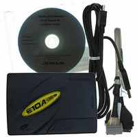
Section 1 Connecting the Emulator with the User System 1.1 Components of the E10A-USB Emulator The H8S/2112F E10A-USB emulator supports the H8S/2112F and H8S/2112RF (hereafter referred to as the MCU unless the description is specific to any of them). Table ...
Page 10
... H8S/2112F and *2 , and H8S/2112RF Test program manual for HS0005KCU01H and HS0005KCU02H Notes: 1. When HS0005KCU02H is purchased, the 36-pin type cable is provided; however not available for this MCU. 2. Additional document for the MCUs supported by the emulator is included. Check the target MCU and refer to its additional document. ...
Page 11
Connecting the E10A-USB Emulator with the User System Before connecting an E10A-USB emulator (hereafter referred to as the emulator) with the user system, a connector must be installed in the user system so that a user system interface cable ...
Page 12
Section 1 Connecting the Emulator with the User System Be sure to place the GND line of the user system interface cable on the GND of the user system with a screw, etc. Failure will result in ...
Page 13
Pin Assignments of the E10A-USB Connector Figure 1.2 shows the pin assignments of the user system connector. Pin 1 mark User system connector Pin 8 Pin 1 Top view Pin 1 mark Figure 1.2 Pin Assignments of the User ...
Page 14
Section 1 Connecting the Emulator with the User System 1.4 Example of Emulator Connection The figure shown below is an example of connecting the user system to the emulator. 14-pin connector with a 2.54-mm pitch (3M Limited: 2514-6002 ...
Page 15
Notes: 1. ETRST#, PE1/ETCK, PE2/ETDI, PE3/ETDO, and PE4/ETMS, are used by the emulator. Pull up and connect the emulator and the MCU pins. User system connector Pins and 6 Figure 1.4 Connection of Emulator and MCU ...
Page 16
Section 1 Connecting the Emulator with the User System 3. RES(in)# of pin 4 of the user system connector is a signal line in which the emulator outputs signals to the MCU. RES(in)# of pin 4 and the user system ...
Page 17
Section 2 Specification of the Emulator’s Software 2.1 Differences between the H8S/2112F and the Emulator 1. When the emulator system is initiated, it initializes the general registers and part of the control registers as shown in table 2.1. The initial ...
Page 18
Section 2 Specification of the Emulator′s Software If the flash memory is rewritten many times, the data will not be erased error message is displayed, exchange the MCU for a new one. 7. Sum Data Displayed in the ...
Page 19
Emulation on Programming or Erasing the Internal Flash Memory A break cannot be generated while the program for programming or erasing the internal flash memory is being called. Note that the following processing also cannot be performed: ⎯ Execution ...
Page 20
... Emulator Driver Selection Table 2.2 shows drivers which can be selected in the [Driver Details] dialog box. Table 2.2 Type Name and Driver Type Name HS0005KCU01H, HS0005KCU02H 2.2.2 Hardware Break Functions Hardware Break Conditions: In the H8S/2112F E10A-USB emulator, eight break conditions (Break condition 1,2,3,4,5,6,7,8) can be set. Table 2.3 lists the items that can be specified. ...
Page 21
Table 2.4 lists the combinations of conditions that can be set in the [Break condition] dialog box. Table 2.4 Conditions Set in [Break condition] Dialog Box Condition Address Bus Dialog Box Condition [Break condition 1] [Break condition 2] [Break condition ...
Page 22
Section 2 Specification of the Emulator′s Software Notes on Setting the Break Condition: 1. When [Step In], [Step Over], or [Step Out] is selected, the settings of Break Condition are disabled. 2. The settings of Break Condition are disabled when ...
Page 23
Note on Using the JTAG Clock (TCK) When the JTAG clock (TCK) is used, set the frequency to lower than that of the system clock. The value of the JTAG clock (TCK) becomes the initial TCK value that has ...
Page 24
Section 2 Specification of the Emulator′s Software Rev. 3.00 Jul. 31, 2009 Page REJ10J1805-0300 ...
Page 25
H8S, H8SX Family E10A-USB Emulator Additional Document for User's Manual Supplementary Information on Using the H8S/2112F and H8S/2112RF Publication Date: Rev.1.00, March 24, 2008 Rev.3.00, July 31, 2009 Published by: Sales Strategic Planning Div. Renesas Technology Corp. Edited by: Customer ...
Page 26
RENESAS SALES OFFICES Refer to "http://www.renesas.com/en/network" for the latest and detailed information. Renesas Technology America, Inc. 450 Holger Way, San Jose, CA 95134-1368, U.S.A Tel: <1> (408) 382-7500, Fax: <1> (408) 382-7501 Renesas Technology Europe Limited Dukes Meadow, Millboard Road, ...
Page 27
...
Page 28
H8S, H8SX Family E10A-USB Emulator Additional Document for User’s Manual Supplementary Information on Using the H8S/2112F and H8S/2112RF 1753, Shimonumabe, Nakahara-ku, Kawasaki-shi, Kanagawa 211-8668 Japan REJ10J1805-0300 ...