XE8000EV110 Semtech, XE8000EV110 Datasheet - Page 182
XE8000EV110
Manufacturer Part Number
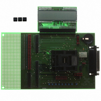
XE8000EV110
Description
EVAL BOARD FOR XE8802AMI035LF
Manufacturer
Semtech
Type
MCUr
Specifications of XE8000EV110
Contents
Fully Assembled Evaluation Board
For Use With/related Products
XE88LC02MI035
Lead Free Status / RoHS Status
Contains lead / RoHS non-compliant


20.11 Capture function
The 16-bit capture register is provided to facilitate frequency measurements. It provides a safe reading mechanism
for the counters A and B when they are running. When the capture function is active, the processor does not read
anymore the counters A and B directly, but instead reads shadow registers located in the capture block. An
interrupt is generated after a capture condition has been met when the shadow register content is updated. The
capture condition is user defined by selecting either internal capture signal sources derived from the prescaler or
from the external PA(2) or PA(3) ports. Both counters use the same capture condition.
When the capture function is active, the A and B counters can either upcount or downcount. They do not count
circularly: they restart at zero or at the maximal value (either 0xFF when not cascaded or 0xFFFF when cascaded)
when respectively an overflow or an underflow condition occurs in the counting. The capture function is also active
on the counters when used to generate PWM signals.
CapFunc(1:0) in register RegCntConfig2 determines if the capture function is enabled or not and selects which
edges of the capture signal source are valid for the capture operation. The source of the capture signal can be
selected by setting CapSel(1:0) in the RegCntConfig2 register. For all sources, rising, falling or both edge
sensitivity can be selected. Table 20-15 shows the capture condition as a function of the setting of these
configuration bits.
CapFunc(1:0) and CapSel(1:0) can be modified only when the counters are stopped otherwise data may be
corrupted during one counter clock cycle.
Due to the synchronization mechanism of the shadow registers and depending on the frequency ratio between the
capture and counter clocks, the interrupts may be generated one or only two counter clock pulses after the effective
capture condition occurred. When the counters A and B are not cascaded and do not operate on the same clock,
the interruptions on IrqA and IrqB which inform that the capture condition was met, may appear at different
moments. In this case, the processor should read the shadow register associated to a counter only if
interruption related to this counter has been detected.
An edge is detected on the capture signals only if the minimal pulse widths of these signals in the low and high
states are higher than a period of the counter clock source.
© Semtech 2006
CapSel(1:0)
11
10
01
00
Selected capture signal
16 K
PA3
PA2
1 K
Table 20-15: Capture condition selection
XE8802 Sensing Machine Data Acquisition MCU
CapFunc
20-10
00
01
10
11
00
01
10
11
00
01
10
11
00
01
10
11
with ZoomingADC™ and LCD driver
Capture disabled
Rising edge
Falling edge
Both edges
Capture disabled
Rising edge
Falling edge
Both edges
Capture disabled
Rising edge
Falling edge
Both edges
Capture disabled
Rising edge
Falling edge
Both edges
Selected condition
-
1 K rising edge
1 K falling edge
2 K
-
16 K rising edge
16 K falling edge
32 K
-
PA3 rising edge
PA3 falling edge
PA3 both edges
-
PA2 rising edge
PA2 falling edge
PA2 both edges
Capture condition
www.semtech.com
the
Related parts for XE8000EV110
Image
Part Number
Description
Manufacturer
Datasheet
Request
R

Part Number:
Description:
EVALUATION BOARD
Manufacturer:
Semtech
Datasheet:
Part Number:
Description:
EVALUATION BOARD
Manufacturer:
Semtech
Datasheet:
Part Number:
Description:
VOLTAGE SUPPRESSOR, TRANSIENT SEMTECH
Manufacturer:
Semtech
Datasheet:

Part Number:
Description:
HIGH VOLTAGE CAPACITORS MONOLITHIC CERAMIC TYPE
Manufacturer:
Semtech Corporation
Datasheet:
Part Number:
Description:
EZ1084CM5.0 AMP POSITIVE VOLTAGE REGULATOR
Manufacturer:
Semtech Corporation
Datasheet:
Part Number:
Description:
3.0 AMP LOW DROPOUT POSITIVE VOLTAGE REGULATORS
Manufacturer:
Semtech Corporation
Datasheet:
Part Number:
Description:
Manufacturer:
Semtech Corporation
Datasheet:
Part Number:
Description:
RailClamp Low Capacitance TVS Diode Array
Manufacturer:
Semtech Corporation
Datasheet:
Part Number:
Description:
Manufacturer:
Semtech Corporation
Datasheet:
Part Number:
Description:
Manufacturer:
Semtech Corporation
Datasheet:
Part Number:
Description:
Manufacturer:
Semtech Corporation
Datasheet:
Part Number:
Description:
Manufacturer:
Semtech Corporation
Datasheet: