XE8000EV110 Semtech, XE8000EV110 Datasheet - Page 102
XE8000EV110
Manufacturer Part Number
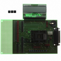
XE8000EV110
Description
EVAL BOARD FOR XE8802AMI035LF
Manufacturer
Semtech
Type
MCUr
Specifications of XE8000EV110
Contents
Fully Assembled Evaluation Board
For Use With/related Products
XE88LC02MI035
Lead Free Status / RoHS Status
Contains lead / RoHS non-compliant


15.7 Interrupts or polling
In receive mode, there are two possibilities to detect condition 1 or 2: the detection of the condition can generate
an interrupt or the registers can be polled (reading and checking the RegUsrtCond1 and RegUsrtCond2 registers
for the status of USRT communication).
15.8 Function description
The bit UsrtEnable in RegUsrtCtrl is used to enable the USRT interface and controls the PB[4] and PB[5] pins.
This bit puts these two port B lines in the open drain configuration requested to use the USRT interface.
If no external pull-ups are added on PB[4] and PB[5], the user can activate internal pull-ups by setting PBPullup[4]
and PBPullup[5] in RegPBPullup.
The bits UsrtEnWaitS0, UsrtEnWaitCond1, UsrtWaitS0 in RegUsrtCtrl are used for transmitter/receiver control
of USRT interface.
Figure 15-3 shows the unconditional clock stretching function which is enabled by setting UsrtEnWaitS0.
When UsrtEnWaitS0 is 1, the S0 line will be maintained at 0 after its falling edge (clock stretching). UsrtWaitS0 is
then set to 1, indicating that the S0 line is forced low. One can release S0 by writing to the RegUsrtBufferS1
register.
The same can be done in combination with condition 1 detection by setting the UsrtEnWaitCond1 bit. Figure 15-4
shows the conditional clock stretching function, which is enabled by setting UsrtEnWaitCond1.
© Semtech 2006
S0
UsrtWaitS0
write Reg UsrtBufferS1
Figure 15-3: S0 Stretching (UsrtEnWaitS0=1)
XE8802 Sensing Machine Data Acquisition MCU
15-5
with ZoomingADC™ and LCD driver
www.semtech.com
Related parts for XE8000EV110
Image
Part Number
Description
Manufacturer
Datasheet
Request
R

Part Number:
Description:
EVALUATION BOARD
Manufacturer:
Semtech
Datasheet:
Part Number:
Description:
EVALUATION BOARD
Manufacturer:
Semtech
Datasheet:
Part Number:
Description:
VOLTAGE SUPPRESSOR, TRANSIENT SEMTECH
Manufacturer:
Semtech
Datasheet:

Part Number:
Description:
HIGH VOLTAGE CAPACITORS MONOLITHIC CERAMIC TYPE
Manufacturer:
Semtech Corporation
Datasheet:
Part Number:
Description:
EZ1084CM5.0 AMP POSITIVE VOLTAGE REGULATOR
Manufacturer:
Semtech Corporation
Datasheet:
Part Number:
Description:
3.0 AMP LOW DROPOUT POSITIVE VOLTAGE REGULATORS
Manufacturer:
Semtech Corporation
Datasheet:
Part Number:
Description:
Manufacturer:
Semtech Corporation
Datasheet:
Part Number:
Description:
RailClamp Low Capacitance TVS Diode Array
Manufacturer:
Semtech Corporation
Datasheet:
Part Number:
Description:
Manufacturer:
Semtech Corporation
Datasheet:
Part Number:
Description:
Manufacturer:
Semtech Corporation
Datasheet:
Part Number:
Description:
Manufacturer:
Semtech Corporation
Datasheet:
Part Number:
Description:
Manufacturer:
Semtech Corporation
Datasheet: