CT-161-CD Fujitsu Semiconductor America Inc, CT-161-CD Datasheet - Page 94
CT-161-CD
Manufacturer Part Number
CT-161-CD
Description
KIT 16LX FOR MB90F387
Manufacturer
Fujitsu Semiconductor America Inc
Series
F²MC-16LXr
Type
MCUr
Specifications of CT-161-CD
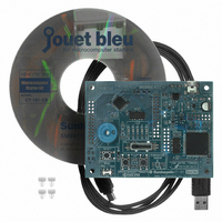
Contents
Board, Cable, CD
For Use With/related Products
MB90F387S
Lead Free Status / RoHS Status
Lead free / RoHS Compliant
Other names
865-1103
Available stocks
Company
Part Number
Manufacturer
Quantity
Price
Company:

Part Number:
CT-161-CD
Manufacturer:
Fujitsu Semiconductor America
Quantity:
135


8.3.2
Let us now create the actual program. According to the procedure described in Appendix
A.1, open the source file "main.c" in "sample.prj," and input the program that is the
circled part in Figure 8-4 Example of program code (main routine)
and Figure 8-5 Example of program code (interrupt routine)
Use all files except main.c without any changes. After the program is input, "build" the
program according to the procedure described in Appendix A.2. If an error is output,
reconfirm that the contents of the program are correct. When the "build" is successful,
"ACCEMIC MDE" starts automatically.
When the "ACCEMIC MDE" window appears, execute the program and check the
operation. For the procedure of the program execution, see Appendix A.3. When the
program starts correctly, check the LEDs. When the temperature of the room where the
operation is performed is between 10 and 20
The number of LEDs lighted varies with the temperature detected by the sensor. For
example, warm up the sensor part using your fingers. When warming up the peripheral
part of the sensor, be aware of the temperature. When it gets hot, it may damage the
board.
voi main(void)
{
}
Creation and execution of the program
__set_il(7);
__EI();
IO_PDR1.byte = 0x1F;
IO_DDR1.byte = 0x1F;
IO_DDR5.bit.D51 = 0;
IO_ICR03.byte = 0x06;
IO_ADCSH.bit.BUSY = 0;
IO_ADER.byte = 0x02;
IO_ADCSL.byte = 0x89;
IO_ADCRLH.byte.ADCRH = 0xF8;
IO_ADCSH.bit.INTE = 1;
IO_ADCSH.bit.STRT = 1;
while(1);
Figure 8-4 Example of program code (main routine)
Program code to be added
-
88
-
o
C, LED 1 and LED 2 are supposed to be on.
(1) Port 1 (LED control) output setting
(2) Port 5 (AD input) input setting
(4) A/D converter initialization
(5) A/D conversion
interrupt permission
(3) Stop A/D converter
(6) A/D conversion starts.
- A/D converter channel setting
- A/D converter mode setting
- A/D sampling condition setting
© Fujitsu
Related parts for CT-161-CD
Image
Part Number
Description
Manufacturer
Datasheet
Request
R

Part Number:
Description:
IC POWER SUPPLY MONITOR 8SOP
Manufacturer:
Fujitsu Semiconductor America Inc
Datasheet:
Part Number:
Description:
IC POWER SUPPLY MONITOR 8SOP
Manufacturer:
Fujitsu Semiconductor America Inc
Datasheet:

Part Number:
Description:
IC MCU 60K FLASH 2KB RAM 52LQFP
Manufacturer:
Fujitsu Semiconductor America Inc
Datasheet:

Part Number:
Description:
IC MCU 32BIT 256KB FLASH 120LQFP
Manufacturer:
Fujitsu Semiconductor America Inc
Datasheet:
Part Number:
Description:
IC CTLR TOUCH SENSOR 12CH 30SSOP
Manufacturer:
Fujitsu Semiconductor America Inc
Datasheet:

Part Number:
Description:
IC CTLR TOUCH SENSOR 12CH 40QFN
Manufacturer:
Fujitsu Semiconductor America Inc
Datasheet:
Part Number:
Description:
SYNTHESIZER PLL DUAL INP 20SSOP
Manufacturer:
Fujitsu Semiconductor America Inc
Datasheet:

Part Number:
Description:
SYNTHESZR PLL 1.1GHZ DUAL 16SSOP
Manufacturer:
Fujitsu Semiconductor America Inc
Datasheet:

Part Number:
Description:
IC SSCG EMI RED 8-SOIC
Manufacturer:
Fujitsu Semiconductor America Inc
Datasheet:

Part Number:
Description:
IC SSCG EMI RED 8-TSSOP
Manufacturer:
Fujitsu Semiconductor America Inc
Datasheet:

Part Number:
Description:
IC SSCG EMI RED 8-SOP
Manufacturer:
Fujitsu Semiconductor America Inc
Datasheet:

Part Number:
Description:
SYNTHESIZER PLL 2.5GHZ 16SSOP
Manufacturer:
Fujitsu Semiconductor America Inc
Datasheet:
Part Number:
Description:
SYNTHESIZER PLL 1.2GHZ 16SSOP
Manufacturer:
Fujitsu Semiconductor America Inc
Datasheet:

Part Number:
Description:
SYNTHESIZER PLL 2.5GHZ 16BCC
Manufacturer:
Fujitsu Semiconductor America Inc
Datasheet:

Part Number:
Description:
IC SSCG EMI RED 8-SOP
Manufacturer:
Fujitsu Semiconductor America Inc
Datasheet: