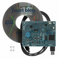
CT-161-CD Fujitsu Semiconductor America Inc, CT-161-CD Datasheet - Page 90

CT-161-CD
Manufacturer Part Number
CT-161-CD
Description
KIT 16LX FOR MB90F387
Manufacturer
Fujitsu Semiconductor America Inc
Series
F²MC-16LXr
Type
MCUr
Specifications of CT-161-CD
Contents
Board, Cable, CD
For Use With/related Products
MB90F387S
Lead Free Status / RoHS Status
Lead free / RoHS Compliant
Other names
865-1103
Available stocks
Company
Part Number
Manufacturer
Quantity
Price
Company:
Part Number:
CT-161-CD
Manufacturer:
Fujitsu Semiconductor America
Quantity:
135
- Current page: 90 of 106
- Download datasheet (4Mb)
shows the peripheral circuit diagram of the "temperature sensor" on the Starter Kit board. In this
circuit, when the resistance of the "temperature sensor" changes, the input voltage of the A/D
converter of the microcomputer also changes. Suppose the resistance of the "temperature sensor" is
R
formula. (The necessary knowledge to calculate it is only Ohm's law.)
TH
. Then, the input voltage of the A/D converter V
Figure 8-2 Peripheral circuit diagram of "temperature sensor" (image)
Table 8.3
voltage summarizes the relationship between the measured temperature from 5 to 50
[Input voltage of the A/D converter]
Because R=10[k Ω ] and Vcc = 5.0[V],
the input voltage to the A/D converter V
formula.
According to the Ohm's law, the current in the circuit I is as shown below:
Therefore, V
Figure 8-2 Peripheral circuit diagram of "temperature sensor" (image)
Relationship between the measured temperature of Starter Kit and A/D input
Microcomput
I
V
V
=
AN
AN
AN1
R
1
1
=
=
V
+
AD
AD
is
CC
R
10000
R
er
TH
TH
5.0
×
×
I
+
R
=
TH
R
R
TH
R
TH
-
+
84
×
R
Pin AN1
-
V
TH
CC
AN1
AN1
[V] can be obtained by using the following
GND
can be calculated by using the following
Vcc
GND
V
Starter Kit board
AN1
R=10[k Ω ]
Temperature
sensor
R=10 k Ω
GND
R
TH
Vcc=5.0[V]
I
© Fujitsu
o
C and
Related parts for CT-161-CD
Image
Part Number
Description
Manufacturer
Datasheet
Request
R

Part Number:
Description:
IC POWER SUPPLY MONITOR 8SOP
Manufacturer:
Fujitsu Semiconductor America Inc
Datasheet:

Part Number:
Description:
IC POWER SUPPLY MONITOR 8SOP
Manufacturer:
Fujitsu Semiconductor America Inc
Datasheet:

Part Number:
Description:
IC MCU 60K FLASH 2KB RAM 52LQFP
Manufacturer:
Fujitsu Semiconductor America Inc
Datasheet:

Part Number:
Description:
IC MCU 32BIT 256KB FLASH 120LQFP
Manufacturer:
Fujitsu Semiconductor America Inc
Datasheet:

Part Number:
Description:
IC CTLR TOUCH SENSOR 12CH 30SSOP
Manufacturer:
Fujitsu Semiconductor America Inc
Datasheet:

Part Number:
Description:
IC CTLR TOUCH SENSOR 12CH 40QFN
Manufacturer:
Fujitsu Semiconductor America Inc
Datasheet:

Part Number:
Description:
SYNTHESIZER PLL DUAL INP 20SSOP
Manufacturer:
Fujitsu Semiconductor America Inc
Datasheet:

Part Number:
Description:
SYNTHESZR PLL 1.1GHZ DUAL 16SSOP
Manufacturer:
Fujitsu Semiconductor America Inc
Datasheet:

Part Number:
Description:
IC SSCG EMI RED 8-SOIC
Manufacturer:
Fujitsu Semiconductor America Inc
Datasheet:

Part Number:
Description:
IC SSCG EMI RED 8-TSSOP
Manufacturer:
Fujitsu Semiconductor America Inc
Datasheet:

Part Number:
Description:
IC SSCG EMI RED 8-SOP
Manufacturer:
Fujitsu Semiconductor America Inc
Datasheet:

Part Number:
Description:
SYNTHESIZER PLL 2.5GHZ 16SSOP
Manufacturer:
Fujitsu Semiconductor America Inc
Datasheet:

Part Number:
Description:
SYNTHESIZER PLL 1.2GHZ 16SSOP
Manufacturer:
Fujitsu Semiconductor America Inc
Datasheet:

Part Number:
Description:
SYNTHESIZER PLL 2.5GHZ 16BCC
Manufacturer:
Fujitsu Semiconductor America Inc
Datasheet:

Part Number:
Description:
IC SSCG EMI RED 8-SOP
Manufacturer:
Fujitsu Semiconductor America Inc
Datasheet:


