ADIS16100/PCB Analog Devices Inc, ADIS16100/PCB Datasheet - Page 7
ADIS16100/PCB
Manufacturer Part Number
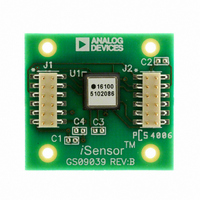
ADIS16100/PCB
Description
BOARD EVALUATION ADIS16100
Manufacturer
Analog Devices Inc
Series
iSensor™r
Specifications of ADIS16100/PCB
Sensor Type
Gyroscope, 1 Axis
Sensing Range
±300°/sec
Interface
SPI Serial
Voltage - Supply
4.75 V ~ 5.25 V
Embedded
No
Utilized Ic / Part
ADIS16100
Silicon Manufacturer
Analog Devices
Application Sub Type
Angular Rate Sensor / Gyroscope
Kit Application Type
Sensing - Motion / Vibration / Shock
Silicon Core Number
ADIS16100
Kit Contents
Board
Lead Free Status / RoHS Status
Contains lead / RoHS non-compliant
For Use With
ADISUSBZ - KIT EVAL ADIS W/SOFTWARE USBADISEVALZ - KIT PC EVALUATION W/SOFTWARE
Sensitivity
-
Lead Free Status / Rohs Status
Not Compliant


PIN CONFIGURATION AND FUNCTION DESCRIPTIONS
Table 4. Pin Function Descriptions
Pin No.
1
2
3
4
5
6
7
8
9
10
11
12
13
14
15
16
1
I = input; O = output; S = power supply.
NOTES
1. NC = NO CONNECT
2. THIS IS NOT AN ACTUAL TOP VIEW, AS THE PINS ARE NOT VISIBLE
FROM THE TOP. THIS IS A LAYOUT VIEW, WHICH REPRESENTS THE PIN
CONFIGURATION, IF THE PACKAGE IS LOOKED THROUGH FROM THE
TOP. THIS CONFIGURATION IS PROVIDED FOR PCB LAYOUT PURPOSES.
DOUT
SCLK
DIN
Figure 4. Pin Configuration, Top Look Through View
Mnemonic
DIN
SCLK
DOUT
NC
RATE
FILT
V
AIN1
AIN2
COM
V
ST2
ST1
V
NC
CS
NC
DRIVE
REF
CC
16
5
LOOK THROUGH
Type
I
I
O
O
I
S
I
I
S
O
I
I
S
I
ADIS16100
(Not to Scale)
PIN 1
INDICATOR
15
6
VIEW
TOP
1
14
7
Description
SPI Data Input.
SPI Serial Clock.
SPI Data Output.
No Connect.
Buffered Analog Output. Represents the angular rate signal.
External Capacitor Connection to Control Bandwidth.
Digital Interface Supply. To simplify interfacing, this can be the receive processing supply of the circuit.
External Analog Input Channel 1. See ADD0 and ADD1 address bits in Table 5.
External Analog Input Channel 2. See ADD0 and ADD1 address bits in Table 5.
Common. Reference point for all circuitry in the ADIS16100.
Precision 2.5 V Reference.
Self-Test Input 2.
Self-Test Input 1.
Analog Power.
No Connect.
Chip Select. Active low. This input frames the serial data transfer and initiates the conversion process.
13
8
V
COM
ST2
AIN2
REF
Rev. D | Page 7 of 16
7.373 BSC
2×
5.010 BSC
1.000 BSC
2.5050 BSC
4×
Figure 5. Second-Level Assembly Pad Layout
16×
8×
3.6865 BSC
8×
0.5000 BSC
ADIS16100
16×
0.6700 BSC
12×
Related parts for ADIS16100/PCB
Image
Part Number
Description
Manufacturer
Datasheet
Request
R

Part Number:
Description:
±1.7g Dual-Axis IMEMS Accelerometer Evaluation Board
Manufacturer:
Analog Devices Inc
Datasheet:

Part Number:
Description:
Inertial Sensor Evaluation System
Manufacturer:
Analog Devices Inc
Datasheet:
Part Number:
Description:
Manufacturer:
Analog Devices Inc
Datasheet:
Part Number:
Description:
Manufacturer:
Analog Devices Inc
Datasheet:
Part Number:
Description:
Manufacturer:
Analog Devices Inc
Datasheet:
Part Number:
Description:
Manufacturer:
Analog Devices Inc
Datasheet:
Part Number:
Description:
Manufacturer:
Analog Devices Inc
Datasheet:
Part Number:
Description:
Manufacturer:
Analog Devices Inc
Datasheet:
Part Number:
Description:
Manufacturer:
Analog Devices Inc
Datasheet:
Part Number:
Description:
Manufacturer:
Analog Devices Inc
Datasheet:
Part Number:
Description:
Manufacturer:
Analog Devices Inc
Datasheet:
Part Number:
Description:
Manufacturer:
Analog Devices Inc
Datasheet:
Part Number:
Description:
Manufacturer:
Analog Devices Inc
Datasheet: