ADIS16100/PCB Analog Devices Inc, ADIS16100/PCB Datasheet - Page 2
ADIS16100/PCB
Manufacturer Part Number
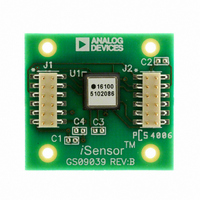
ADIS16100/PCB
Description
BOARD EVALUATION ADIS16100
Manufacturer
Analog Devices Inc
Series
iSensor™r
Specifications of ADIS16100/PCB
Sensor Type
Gyroscope, 1 Axis
Sensing Range
±300°/sec
Interface
SPI Serial
Voltage - Supply
4.75 V ~ 5.25 V
Embedded
No
Utilized Ic / Part
ADIS16100
Silicon Manufacturer
Analog Devices
Application Sub Type
Angular Rate Sensor / Gyroscope
Kit Application Type
Sensing - Motion / Vibration / Shock
Silicon Core Number
ADIS16100
Kit Contents
Board
Lead Free Status / RoHS Status
Contains lead / RoHS non-compliant
For Use With
ADISUSBZ - KIT EVAL ADIS W/SOFTWARE USBADISEVALZ - KIT PC EVALUATION W/SOFTWARE
Sensitivity
-
Lead Free Status / Rohs Status
Not Compliant


ADIS16100
TABLE OF CONTENTS
Features .............................................................................................. 1
Applications ....................................................................................... 1
General Description ......................................................................... 1
Functional Block Diagram .............................................................. 1
Revision History ............................................................................... 2
Specifications ..................................................................................... 3
Absolute Maximum Ratings ............................................................ 6
Pin Configuration and Function Descriptions ............................. 7
Typical Performance Characteristics ............................................. 8
Theory of Operation ...................................................................... 11
REVISION HISTORY
6/09—Rev. C to Rev. D
Changes to Table 1 ............................................................................ 3
Changes to Table 10 and Table 11 ................................................ 13
Added Applications Information Section ................................... 14
1/08—Rev. B to Rev. C
Changes Features .............................................................................. 1
Changes to Table 1 ............................................................................ 4
Changes to Table 3 ............................................................................ 6
Changes to Layout and Table 4 ....................................................... 7
Changes to Captions Figure 12 to Figure 15 ................................. 9
Changes to Self-Test Function Section ........................................ 11
Changes to Figure 22 Caption ....................................................... 12
Changes to Table 6, Table 7, Table 8, and Table 9 ....................... 13
6/07—Rev. A to Rev. B
Changes to Table 1 ............................................................................ 3
Changes to Table 2 ............................................................................ 5
Changes to Absolute Maximum Ratings ....................................... 6
Changes to Table 4 ............................................................................ 7
Added Figure 5 .................................................................................. 7
Changes to Theory of Operation Section .................................... 11
Added Basic Operation Section .................................................... 12
Deleted Second Level Assembly Section ..................................... 14
Timing Specifications .................................................................. 5
ESD Caution .................................................................................. 6
Supply and Common Considerations ..................................... 11
Rev. D | Page 2 of 16
Basic Operation .............................................................................. 12
Applications Information .............................................................. 14
Outline Dimensions ....................................................................... 15
5/06—Rev. 0 to Rev. A
Changes to Table 1 ............................................................................. 4
Changes to Setting Bandwidth Section ....................................... 11
Changes to Table 9 and Table 10 .................................................. 13
1/06—Revision 0: Initial Version
Increasing Measurement Range ............................................... 11
Setting Bandwidth ...................................................................... 11
Self-Test Function ...................................................................... 11
Rate Sensitive Axis ..................................................................... 11
Serial Peripheral Interface (SPI) ............................................... 12
Assembly ...................................................................................... 14
Interface board ............................................................................ 14
Ordering Guide .......................................................................... 15
Related parts for ADIS16100/PCB
Image
Part Number
Description
Manufacturer
Datasheet
Request
R

Part Number:
Description:
±1.7g Dual-Axis IMEMS Accelerometer Evaluation Board
Manufacturer:
Analog Devices Inc
Datasheet:

Part Number:
Description:
Inertial Sensor Evaluation System
Manufacturer:
Analog Devices Inc
Datasheet:
Part Number:
Description:
Manufacturer:
Analog Devices Inc
Datasheet:
Part Number:
Description:
Manufacturer:
Analog Devices Inc
Datasheet:
Part Number:
Description:
Manufacturer:
Analog Devices Inc
Datasheet:
Part Number:
Description:
Manufacturer:
Analog Devices Inc
Datasheet:
Part Number:
Description:
Manufacturer:
Analog Devices Inc
Datasheet:
Part Number:
Description:
Manufacturer:
Analog Devices Inc
Datasheet:
Part Number:
Description:
Manufacturer:
Analog Devices Inc
Datasheet:
Part Number:
Description:
Manufacturer:
Analog Devices Inc
Datasheet:
Part Number:
Description:
Manufacturer:
Analog Devices Inc
Datasheet:
Part Number:
Description:
Manufacturer:
Analog Devices Inc
Datasheet:
Part Number:
Description:
Manufacturer:
Analog Devices Inc
Datasheet: