ADIS16100/PCB Analog Devices Inc, ADIS16100/PCB Datasheet - Page 3
ADIS16100/PCB
Manufacturer Part Number
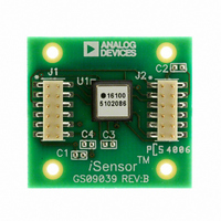
ADIS16100/PCB
Description
BOARD EVALUATION ADIS16100
Manufacturer
Analog Devices Inc
Series
iSensor™r
Specifications of ADIS16100/PCB
Sensor Type
Gyroscope, 1 Axis
Sensing Range
±300°/sec
Interface
SPI Serial
Voltage - Supply
4.75 V ~ 5.25 V
Embedded
No
Utilized Ic / Part
ADIS16100
Silicon Manufacturer
Analog Devices
Application Sub Type
Angular Rate Sensor / Gyroscope
Kit Application Type
Sensing - Motion / Vibration / Shock
Silicon Core Number
ADIS16100
Kit Contents
Board
Lead Free Status / RoHS Status
Contains lead / RoHS non-compliant
For Use With
ADISUSBZ - KIT EVAL ADIS W/SOFTWARE USBADISEVALZ - KIT PC EVALUATION W/SOFTWARE
Sensitivity
-
Lead Free Status / Rohs Status
Not Compliant


SPECIFICATIONS
T
Table 1.
Parameter
SENSITIVITY
NULL
NOISE PERFORMANCE
FREQUENCY RESPONSE
SELF-TEST INPUTS
TEMPERATURE SENSOR
2.5 V REFERENCE
LOGIC INPUTS
ANALOG INPUTS
A
Dynamic Range
Initial
Change Over Temperature
Nonlinearity
Initial
Change Over Temperature
Turn-On Time
Linear Acceleration Effect
Voltage Sensitivity
Total Noise
Rate Noise Density
3 dB Bandwidth (User-Selectable)
Sensor Resonant Frequency
ST1 Rateout Response
ST2 Rateout Response
Logic 1 Input Voltage
Logic 0 Input Voltage
Input Impedance
Reading at 298 K
Scale Factor
Voltage Value
Load Drive to Ground
Load Regulation
Power Supply Rejection
Temperature Drift
Input High Voltage, V
Input Low Voltage, V
Input Current, I
Input Capacitance, C
Resolution
Integral Nonlinearity
Differential Nonlinearity
Offset Error
Gain Error
Input Voltage Range
Leakage Current
Input Capacitance
Full Power Bandwidth
= 25°C, V
CC
= V
IN
2
DRIVE
INL
IN
INH
= 5 V, angular rate = 0°/sec, C
5
5
3
3
4
Conditions
Full-scale range over specifications range
Clockwise rotation is positive output,
T
V
Best fit straight line
Nominal 0°/sec output is 2048 LSB
V
Power-on to ±0.5°/sec of final value
Any axis
V
0.1 Hz to 40 Hz; no averaging
@ 25°C
C
ST1 pin from Logic 0 to Logic 1
ST2 pin from Logic 0 to Logic 1
Standard high logic level definition
Standard low logic level definition
To common
Proportional to absolute temperature
Source
0 μA < I
V
Delta from 25°C
Typically 10 nA
For V
A
CC
CC
CC
CC
OUT
= −40°C to +85°C
= V
= V
= V
= V
= 0 μF
IN
DRIVE
DRIVE
DRIVE
DRIVE
< V
OUT
CC
< 100 μA
= 4.75 V to 5.25 V
= 4.75 V to 5.25 V
= 4.75 V to 5.25 V
= 4.75 V to 5.25 V
OUT
= 0 μF, ±1 g, unless otherwise noted.
Rev. D | Page 3 of 16
Min
±300
0.2212
−42
−121
+121
3.3
2.45
0.7 × V
−1
−2
−2
−8
−2
0
−1
1
DRIVE
Typ
0.2439
±5
0.15
±10
35
0.2
±1
0.43
0.05
40
14
−221
+221
50
2048
0.1453
2.5
100
5.0
1.0
5.0
10
12
20
8
Max
0.2717
+42
−376
+376
1.7
2.55
0.3 × V
+1
+2
+2
+8
+2
V
+1
REF
× 2
1
DRIVE
ADIS16100
Unit
°/sec
°/sec/LSB
%
%FS
°/sec
°/sec
ms
°/sec/g
°/sec/V
°/sec rms
°/sec/√Hz
Hz
kHz
LSB
LSB
V
V
kΩ
LSB
K/LSB
V
μA
mV/mA
mV/V
mV
V
V
μA
pF
Bits
LSB
LSB
LSB
LSB
V
μA
pF
MHz
Related parts for ADIS16100/PCB
Image
Part Number
Description
Manufacturer
Datasheet
Request
R

Part Number:
Description:
±1.7g Dual-Axis IMEMS Accelerometer Evaluation Board
Manufacturer:
Analog Devices Inc
Datasheet:

Part Number:
Description:
Inertial Sensor Evaluation System
Manufacturer:
Analog Devices Inc
Datasheet:
Part Number:
Description:
Manufacturer:
Analog Devices Inc
Datasheet:
Part Number:
Description:
Manufacturer:
Analog Devices Inc
Datasheet:
Part Number:
Description:
Manufacturer:
Analog Devices Inc
Datasheet:
Part Number:
Description:
Manufacturer:
Analog Devices Inc
Datasheet:
Part Number:
Description:
Manufacturer:
Analog Devices Inc
Datasheet:
Part Number:
Description:
Manufacturer:
Analog Devices Inc
Datasheet:
Part Number:
Description:
Manufacturer:
Analog Devices Inc
Datasheet:
Part Number:
Description:
Manufacturer:
Analog Devices Inc
Datasheet:
Part Number:
Description:
Manufacturer:
Analog Devices Inc
Datasheet:
Part Number:
Description:
Manufacturer:
Analog Devices Inc
Datasheet:
Part Number:
Description:
Manufacturer:
Analog Devices Inc
Datasheet: