EVK2160A Atmel, EVK2160A Datasheet - Page 8
EVK2160A
Manufacturer Part Number
EVK2160A
Description
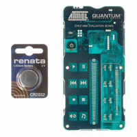
KIT EVAL FOR AT42QT2160-MMU
Manufacturer
Atmel
Series
Quantum, QTouch™r
Specifications of EVK2160A
Sensor Type
Touch, Capacitive
Sensing Range
8 Buttons/Keys, Slider
Interface
I²C
Voltage - Supply
1.8 V ~ 5.5 V
Embedded
No
Utilized Ic / Part
AT42QT2160
Silicon Manufacturer
Atmel
Silicon Core Number
AT42QT2160-MMU
Kit Application Type
Sensing - Touch / Proximity
Application Sub Type
Capacitive Touch
Kit Contents
Board CD Docs
Rohs Compliant
Yes
Lead Free Status / RoHS Status
Lead free / RoHS Compliant
Sensitivity
-
Lead Free Status / Rohs Status
Supplier Unconfirmed
Other names
427-1141
Available stocks
Company
Part Number
Manufacturer
Quantity
Price
Company:

Part Number:
EVK2160A
Manufacturer:
Atmel
Quantity:
135


Dwell time is the duration in which charge coupled from X to Y is captured
(Figure 4-4
on page
7). Increasing Rx values will cause the leading edge of the X pulses to increasingly roll
off, causing the loss of captured charge (and hence loss of signal strength) from the keys.
The dwell time is a minimum of 250 ns. If the X pulses have not settled within 250 ns, key gain
will be reduced; if this happens, either the stray capacitance on the X line(s) should be reduced
(by a layout change, for example by reducing X line exposure to nearby ground planes or
traces), or, the Rx resistor needs to be reduced in value (or a combination of both approaches).
One way to determine X line settling time is to monitor the fields using a patch of metal foil or a
small coin over the key
(Figure
4-5). Only one key along a particular X line needs to be
observed, 250 ns dwell time should exceed the observed 95 percent settling of the X-pulse by
25 percent or more.
In almost all cases, Ry should be set equal to Rx, which will ensure that the charge on the Y line
is fully captured into the Cs capacitor.
Figure 4-5.
Probing X-Drive Waveforms With a Coin
4.8
Key Design
Circuits can be constructed out of a variety of materials including conventional FR-4, Flexible
Printed Circuit Boards (FPCB), silver silk-screened on PET plastic film, and even inexpensive
punched single-sided CEM-1 and FR-2.
The actual internal pattern style is not as important as the need to achieve regular X and Y
widths and spacings of sufficient size to cover the desired graphical key area or a little bit more;
~3mm oversize is acceptable in most cases, since the key’s electric fields drop off near the
edges anyway. The overall key size can range from 6mm x 6mm up to 100mm x 100mm but
these are not hard limits. The keys can be any shape including round, rectangular, square, etc.
The internal pattern can be interdigitated as shown in
Figure
4-6.
For small, dense keypads, electrodes such as shown in the lower half of
Figure 4-6
can be used.
Where the panels are thin (under 2 mm thick) the electrode density can be quite high.
AT42QT2160
8
9502A–AT42–07/08
Related parts for EVK2160A
Image
Part Number
Description
Manufacturer
Datasheet
Request
R

Part Number:
Description:
DEV KIT FOR AVR/AVR32
Manufacturer:
Atmel
Datasheet:

Part Number:
Description:
INTERVAL AND WIPE/WASH WIPER CONTROL IC WITH DELAY
Manufacturer:
ATMEL Corporation
Datasheet:
Part Number:
Description:
Low-Voltage Voice-Switched IC for Hands-Free Operation
Manufacturer:
ATMEL Corporation
Datasheet:
Part Number:
Description:
MONOLITHIC INTEGRATED FEATUREPHONE CIRCUIT
Manufacturer:
ATMEL Corporation
Datasheet:
Part Number:
Description:
AM-FM Receiver IC U4255BM-M
Manufacturer:
ATMEL Corporation
Datasheet:
Part Number:
Description:
Monolithic Integrated Feature Phone Circuit
Manufacturer:
ATMEL Corporation
Datasheet:
Part Number:
Description:
Multistandard Video-IF and Quasi Parallel Sound Processing
Manufacturer:
ATMEL Corporation
Datasheet:
Part Number:
Description:
High-performance EE PLD
Manufacturer:
ATMEL Corporation
Datasheet:
Part Number:
Description:
8-bit Flash Microcontroller
Manufacturer:
ATMEL Corporation
Datasheet:
Part Number:
Description:
2-Wire Serial EEPROM
Manufacturer:
ATMEL Corporation
Datasheet: