EVK2160A Atmel, EVK2160A Datasheet - Page 40
EVK2160A
Manufacturer Part Number
EVK2160A
Description
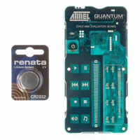
KIT EVAL FOR AT42QT2160-MMU
Manufacturer
Atmel
Series
Quantum, QTouch™r
Specifications of EVK2160A
Sensor Type
Touch, Capacitive
Sensing Range
8 Buttons/Keys, Slider
Interface
I²C
Voltage - Supply
1.8 V ~ 5.5 V
Embedded
No
Utilized Ic / Part
AT42QT2160
Silicon Manufacturer
Atmel
Silicon Core Number
AT42QT2160-MMU
Kit Application Type
Sensing - Touch / Proximity
Application Sub Type
Capacitive Touch
Kit Contents
Board CD Docs
Rohs Compliant
Yes
Lead Free Status / RoHS Status
Lead free / RoHS Compliant
Sensitivity
-
Lead Free Status / Rohs Status
Supplier Unconfirmed
Other names
427-1141
Available stocks
Company
Part Number
Manufacturer
Quantity
Price
Company:

Part Number:
EVK2160A
Manufacturer:
Atmel
Quantity:
135


9.6
9.7
40
Slider
Adjacent Key Suppression (AKS) Technology
AT42QT2160
A change in burst length should be followed by a calibration command (set the calibration byte to
a nonzero value) to ensure reliable operation. It is also possible to adjust the sensitivity using the
negative threshold for that key. Note that thresholds below 6 counts may cause sensitivity to
noise and thresholds above 12 counts will require longer burst lengths than strictly necessary.
All unused keys should be switched off by setting their burst lengths to zero. This will reduce the
power requirements of the device.
A group of keys on the Y0 line can be configured as a slider. These have to be placed in
numerical order starting with X0 and with no missing keys in the sequence. The keys should be
5-7mm wide along the length of the slider for good linearity. The number of keys needed in a
slider will simply be the number of the size required to form the desired slider length.
The slider can now be enabled by setting the NUM_KEYS bits in Slider Control byte to the
number of keys which are used in the slider. This can be from 2 to 8 keys. For example, to
enable a slider of five keys, set NUM_KEYS to five. Note that the higher the resolution, the more
keys will be required to get a stable response out of the slider. As a general rule, the number of
keys must be at least the number of bits, e.g. at least 4 keys for a 4 bit slider.
Now the slider is enabled, touching it will result in a slider position being reported in the Slider
Touch Position byte. Note that the keys forming the slider will still cause key detections and will
still report their status in the key status registers.
If the slider position is noisy, try reducing the panel thickness or increasing the sensitivities of the
keys forming the slider, to get more signal for positional calculations. Increasing the hysteresis
(Section 4.2 on page
Keys within the same slider are normally in the same AKS group and have the same burst length
and threshold.
Adjacent Key Suppression (AKS) technology is a patented method to detect which key is
pressed, when keys are located close together. A touch in a group of AKS keys will only be
indicated on the key with the largest signal. This is assumed to be the intended key.
Once a key in an AKS group is in detect, there can be no further detections on keys in that group
until the key is released. By default, the AKS technique is disabled on all keys; therefore, the
keys can detect, regardless of the state of any other keys.
The AKS technology works slightly differently when keys are in a slider which act like a single
AKS object. Any number of keys can go into detect with a slider but if any keys within one of
these objects are in detect then the AKS technology will lock out anything else in the same AKS
group. Similarly, a key in the same AKS group as the slider can lock out the slider as a whole
object.
Note: for normal operation all keys in the slider should be placed in the same AKS group.
5) will also help.
9502A–AT42–07/08
Related parts for EVK2160A
Image
Part Number
Description
Manufacturer
Datasheet
Request
R

Part Number:
Description:
DEV KIT FOR AVR/AVR32
Manufacturer:
Atmel
Datasheet:

Part Number:
Description:
INTERVAL AND WIPE/WASH WIPER CONTROL IC WITH DELAY
Manufacturer:
ATMEL Corporation
Datasheet:
Part Number:
Description:
Low-Voltage Voice-Switched IC for Hands-Free Operation
Manufacturer:
ATMEL Corporation
Datasheet:
Part Number:
Description:
MONOLITHIC INTEGRATED FEATUREPHONE CIRCUIT
Manufacturer:
ATMEL Corporation
Datasheet:
Part Number:
Description:
AM-FM Receiver IC U4255BM-M
Manufacturer:
ATMEL Corporation
Datasheet:
Part Number:
Description:
Monolithic Integrated Feature Phone Circuit
Manufacturer:
ATMEL Corporation
Datasheet:
Part Number:
Description:
Multistandard Video-IF and Quasi Parallel Sound Processing
Manufacturer:
ATMEL Corporation
Datasheet:
Part Number:
Description:
High-performance EE PLD
Manufacturer:
ATMEL Corporation
Datasheet:
Part Number:
Description:
8-bit Flash Microcontroller
Manufacturer:
ATMEL Corporation
Datasheet:
Part Number:
Description:
2-Wire Serial EEPROM
Manufacturer:
ATMEL Corporation
Datasheet: