EVK2160A Atmel, EVK2160A Datasheet - Page 33
EVK2160A
Manufacturer Part Number
EVK2160A
Description
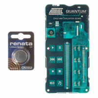
KIT EVAL FOR AT42QT2160-MMU
Manufacturer
Atmel
Series
Quantum, QTouch™r
Specifications of EVK2160A
Sensor Type
Touch, Capacitive
Sensing Range
8 Buttons/Keys, Slider
Interface
I²C
Voltage - Supply
1.8 V ~ 5.5 V
Embedded
No
Utilized Ic / Part
AT42QT2160
Silicon Manufacturer
Atmel
Silicon Core Number
AT42QT2160-MMU
Kit Application Type
Sensing - Touch / Proximity
Application Sub Type
Capacitive Touch
Kit Contents
Board CD Docs
Rohs Compliant
Yes
Lead Free Status / RoHS Status
Lead free / RoHS Compliant
Sensitivity
-
Lead Free Status / Rohs Status
Supplier Unconfirmed
Other names
427-1141
Available stocks
Company
Part Number
Manufacturer
Quantity
Price
Company:

Part Number:
EVK2160A
Manufacturer:
Atmel
Quantity:
135


7.22
7.23
9502A–AT42–07/08
Address 70...71: GPIO/GPO Drive
Address 73: GPIO Direction
Table 7-23.
Table 7-24.
The burst length is the number of times the charge-transfer (QT) process is performed on a
given key. Each QT process is simply the pulsing of an X line once, with a corresponding Y line
enabled to capture the resulting charge passed through the key’s capacitance Cx.
Increasing burst length directly affects key sensitivity. This occurs because the accumulation of
charge in the charge integrator is directly linked to the burst length. The burst length of each key
can be set individually, allowing for direct digital control over the signal gains of each key
individually.
Apparent touch sensitivity is also controlled by the Negative Threshold level (NTHR). Burst
length and NTHR interact; normally burst lengths should be kept as short as possible to reduce
scan time and limit RF emissions, but NTHR should be kept above 6 to reduce false detections
due to external noise. The detection integrator mechanism also helps to prevent false
detections.
Note: setting a burst length of zero for a specific key, disables that key.
Typical values: 8 to 32 (32 to 128 burst pulses)
Default: 4 (16 burst pulses)
If the GPIOs are set to outputs, the drive for the individual GPIO is set according to the
corresponding bit in GPIO Drive bytes. Setting the bit to 1 will drive the corresponding GPIO pin
to Vdd, while setting it to 0, will drive the corresponding GPIO pin to ground.
Enabling PWM on a GPIO pin will override the drive on the pin.
Shared X line GPOs will be only driven when not doing any measurements. During
measurements, burst pulses will be driven from the X lines, make sure that the driven device will
not be affected.
Default: 0 (All driven low)
Sets the direction of the GPIOs: 1 = driven outputs, 0 = floating inputs.
If set as inputs, the GPIO will only be read every 16ms (fixed cycle time).
Address
Address
70
71
73
GPIO/GPO Drive
GPIO Direction
b7
X7
b7
0
0
X6
b6
b6
0
0
X5
b5
b5
0
0
GPIO3
GPIO3
b4
X4
b4
GPIO2
GPIO2
b3
X3
b3
GPIO1
GPIO1
b2
X2
b2
AT42QT2160
X1
b1
b1
0
0
X0
b0
b0
0
0
33
Related parts for EVK2160A
Image
Part Number
Description
Manufacturer
Datasheet
Request
R

Part Number:
Description:
DEV KIT FOR AVR/AVR32
Manufacturer:
Atmel
Datasheet:

Part Number:
Description:
INTERVAL AND WIPE/WASH WIPER CONTROL IC WITH DELAY
Manufacturer:
ATMEL Corporation
Datasheet:
Part Number:
Description:
Low-Voltage Voice-Switched IC for Hands-Free Operation
Manufacturer:
ATMEL Corporation
Datasheet:
Part Number:
Description:
MONOLITHIC INTEGRATED FEATUREPHONE CIRCUIT
Manufacturer:
ATMEL Corporation
Datasheet:
Part Number:
Description:
AM-FM Receiver IC U4255BM-M
Manufacturer:
ATMEL Corporation
Datasheet:
Part Number:
Description:
Monolithic Integrated Feature Phone Circuit
Manufacturer:
ATMEL Corporation
Datasheet:
Part Number:
Description:
Multistandard Video-IF and Quasi Parallel Sound Processing
Manufacturer:
ATMEL Corporation
Datasheet:
Part Number:
Description:
High-performance EE PLD
Manufacturer:
ATMEL Corporation
Datasheet:
Part Number:
Description:
8-bit Flash Microcontroller
Manufacturer:
ATMEL Corporation
Datasheet:
Part Number:
Description:
2-Wire Serial EEPROM
Manufacturer:
ATMEL Corporation
Datasheet: