RDK-193 Power Integrations, RDK-193 Datasheet - Page 15
RDK-193
Manufacturer Part Number
RDK-193
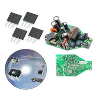
Description
KIT REF DESIGN FOR LNK403EG
Manufacturer
Power Integrations
Type
Power Factor Correctionr
Specifications of RDK-193
Current - Output / Channel
330mA
Outputs And Type
1, Non-Isolated
Voltage - Output
21V
Features
Dimmable with Standard TRIAC Dimmer, Power Factor Correction
Voltage - Input
90 ~ 265VAC
Utilized Ic / Part
LNK403EG
Input Voltage
90 V to 265 V
Output Voltage
21 V
Product
Power Management Modules
Lead Free Status / RoHS Status
Lead free / RoHS Compliant
For Use With/related Products
LNK403EG
Other names
596-1307
Available stocks
Company
Part Number
Manufacturer
Quantity
Price
Company:

Part Number:
RDK-193
Manufacturer:
Power Integrations
Quantity:
135


7.4 Transformer Build Diagram
7.5 Transformer Construction
Page 15 of 41
Preparation
Insulation
Insulation
Insulation
Insulation
Assembly
Bobbin
Pins Side
WD 1
WD 2
WD 3
WD 4
Final
W4 - Finish (FL1)
W3 - Finish (FL3)
W2 - Finish (P2)
W3 - Start (FL2)
W2 - Start (P6)
W1 - Start (P1)
Place the bobbin item [2] on the mandrel such that pin side on the left side. Winding
direction is the clockwise direction.
Start at pin 1, wind 64 turns of #35 AWG item [3] from left to right two layers. At the last
turn exit the same slot, leave enough length wire floating to wind next 64 turns in WD4.
Apply one layer of tape [6] for insulation.
Start at pin 6, wind 26 turns of #36 AWG [4] wire from left to right. Finish at pin 2.
Apple one layer of tape [6] for insulation.
Leave about 1” of wire item [5], use small tape to mark as FL2, enter into slot of
secondary side of bobbin, wind 22 turns in two layers. At the last turn exit the same slot,
leave about 1”, and mark as FL3.
Apple one layer of tape [6] for insulation.
Continue to wind with floating wire, 64 turns of #35 AWG from left to right two layers.
Leave 1” and mark as FL1
Apply three layers of tape [6] for insulation.
Cut FL1, FL2, FL3 wire length to 0.75”. Grind core. Assemble core and varnish using
item [7].
Figure 6 – Transformer Build Diagram.
Tel: +1 408 414 9200 Fax: +1 408 414 9201
Power Integrations
www.powerint.com
1L Tape
3L Tape
1L Tape
1L Tape
Related parts for RDK-193
Image
Part Number
Description
Manufacturer
Datasheet
Request
R

Part Number:
Description:
KIT REF DESIGN FOR LNK457D
Manufacturer:
Power Integrations
Datasheet:

Part Number:
Description:
REFERENCE DESIGN LINKSWITCH-PH
Manufacturer:
Power Integrations
Datasheet:

Part Number:
Description:
KIT REF DESIGN FOR LNK406EG
Manufacturer:
Power Integrations
Datasheet:

Part Number:
Description:
KIT REF DESIGN LINKSWITCH-CV
Manufacturer:
Power Integrations
Datasheet:

Part Number:
Description:
KIT REF DESIGN LINKSWITCH 2
Manufacturer:
Power Integrations
Datasheet:

Part Number:
Description:
Specifications: Family: Eval Boards - DC/DC & AC/DC (Off-Line) SMPS ; Series: HiperLCS™ ; Main Purpose: DC/DC, Step Down ; Outputs and Type: 1, Isolated ; Power - Output: 150W ; Voltage - Output: 24V ; Current - Output: 6.25A ; Voltage - Input:
Manufacturer:
Power Integrations, Inc.
Datasheet:

Part Number:
Description:
KIT DESIGN REF TINYSWITCH-III
Manufacturer:
Power Integrations
Datasheet:

Part Number:
Description:
KIT DESIGN REF LINKSWITCH LP
Manufacturer:
Power Integrations
Datasheet:

Part Number:
Description:
KIT REF DESIGN LED LINKSWITCH TN
Manufacturer:
Power Integrations
Datasheet:
Part Number:
Description:
KIT REF DESIGN PG LINKSWITCH-II
Manufacturer:
Power Integrations
Datasheet:
Part Number:
Description:
REFERENCE DESIGN LINKSWITCH-PL
Manufacturer:
Power Integrations
Datasheet:
Part Number:
Description:
REFERENCE DESIGN LINKSWITCH-PH
Manufacturer:
Power Integrations
Datasheet:

Part Number:
Description:
KIT REF DESIGN 36-72W MOTOR DRVR
Manufacturer:
Power Integrations
Datasheet:
Part Number:
Description:
Specifications: Manufacturer: Power Integrations ; Output Voltage: 380 VDC ; Input / Supply Voltage (Max): 264 VAC ; Input / Supply Voltage (Min): 90 VAC ; Mounting Style: Through Hole ; Output Current: 0.913 A ; Output Power: 347 W
Manufacturer:
Power Integrations, Inc.

Part Number:
Description:
KIT REF DESIGN TOP HX FOR TOP258
Manufacturer:
Power Integrations
Datasheet: