NCP1028LEDGEVB ON Semiconductor, NCP1028LEDGEVB Datasheet - Page 19
NCP1028LEDGEVB
Manufacturer Part Number
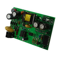
NCP1028LEDGEVB
Description
EVAL BOARD FOR NCP1028LEDG
Manufacturer
ON Semiconductor
Specifications of NCP1028LEDGEVB
Design Resources
NCP1028LEDGEVB BOM CP1028LEDGEVB Gerber Files NCP1028LED EVB Schematic
Current - Output / Channel
720mA
Outputs And Type
1, Isolated
Voltage - Output
18V
Voltage - Input
90 ~ 265VAC
Utilized Ic / Part
NCP1028
Core Chip
NCP1028
Topology
Flyback
No. Of Outputs
1
Output Current
720mA
Output Voltage
18V
Development Tool Type
Hardware - Eval/Demo Board
Leaded Process Compatible
Yes
Mcu Supported Families
NCP1028
Rohs Compliant
Yes
Lead Free Status / RoHS Status
Lead free / RoHS Compliant
Features
-
Lead Free Status / Rohs Status
Lead free / RoHS Compliant
For Use With/related Products
NCP1028LEDG
Other names
NCP1028LEDGEVBOS


Designing the Auxiliary Winding
applied on the V
shown on Figure 33. Care must be taken to avoid injecting
too much current when the clamp is activated. The
insertion of a resistor (
and the V
internal 8.7 V zener diode during an overshoot for instance
(absolute maximum current is 15 mA. Please note that
there cannot be bad interaction between the clamping
voltage of the internal zener and VCC
clamping voltage is actually built on top of VCC
fixed amount of offset (200 mV typical).
carefully selected to avoid disturbing the V
load conditions. The below lines detail how to evaluate the
R
applications often puzzles the designer. Actually, if a
SMPS operated at nominal load can deliver an auxiliary
voltage of an arbitrary 16 V (V
below 10 V (V
the recurrence of the switching pulses expands so much that
the low frequency re-fueling rate of the V
not enough to keep a proper auxiliary voltage. Figure 34
portrays a typical scope shot of a SMPS entering deep
standby (output un-loaded). Thus, care must be taken when
keep V
purposely select a V
before, experience shows that a 40% decrease can be seen
on auxiliary windings from nominal operation down to
standby mode. Let's select a nominal auxiliary winding of
20 V to offer sufficient margin regarding 8.0 V when in
standby (R
limit
A NCP1028 internal arrangement clamps the voltage
Self-supplying controllers in extremely low standby
Since
value.
auxiliary
R
limit
CC
limit
shall not bother the controller in standby, e.g.
pin is thus mandatory not to damage the
stby
also drops voltage in standby…).
to around 8.0 V (as selected above), we
CC
) when entering standby. This is because
nom
pin. It uses an active shunt circuitry as
R
limit
well above this value. As explained
) between the auxiliary dc level
Figure 33. A more detailed view of the NCP1028 offers better
nom
V
insight on how to properly wire an auxiliary winding.
clamp
), this voltage can drop
V
V
CCON
CC(min)
= 8.7 V Typ.
R
= 8.5 V
CC
+
CC
ON
limit
= 7.5 V
+
in low / light
capacitor is
+
-
since this
ON
should be
+
-
http://onsemi.com
with a
NCP1028
19
Ground
Drain
I > 6 mA
V
Startup
Source
CC
calculating R
entering standby. Otherwise, the converter will enter burst
mode as it will sense an UVLO condition. Based on these
recommendations, we are able to bound
equations:
Where:
V
V
ICC
without damaging the controller (15 mA).
ICC1 is the controller consumption. This number slightly
decreases compared to ICC1 from the spec since the part
in standby does almost not switch. It is around 1.0 mA for
the 65 kHz version and 1.4 mA for the 100 kHz one.
VCC
must be maintained to keep the controller away from the
UVLO trip point. It is good to obtain around 8.0 V in order
to offer an adequate design margin, e.g. to not reactivate the
startup source (which is not a problem in itself if low
standby power does not matter).
which
order to include a safety margin.
20-8.7
10 m
nom
stdby
Plugging the values in Equation 3 gives the limits within
We purposely limited the injected current to 10 mA in
max
(min)
+
is the auxiliary voltage at nominal load.
V nom -V clamp
R
R
is the auxiliary voltage when standby is entered.
C
v R limit v 12-8
limit
limit
VCC
is the maximum current you can inject in the pin
I CCmax
is the level above which the auxiliary voltage
limit
shall be selected:
+
C
D1
not to drop too much voltage over it when
AUX
1 m
v R limit v
L
aux
, that is
to
V stby -V CCON
say : 1.3 kW t R limit
ICC1
t 4 kW.
R
limit
between two
(eq. 3)
Related parts for NCP1028LEDGEVB
Image
Part Number
Description
Manufacturer
Datasheet
Request
R

Part Number:
Description:
Low Dropout Linear Regulator Controller
Manufacturer:
ON Semiconductor
Datasheet:

Part Number:
Description:
EVAL BOARD FOR NCP102MBG
Manufacturer:
ON Semiconductor
Datasheet:
Part Number:
Description:
ON Semiconductor [VOLTAGE REGULATOR]
Manufacturer:
ON Semiconductor
Datasheet:
Part Number:
Description:
357-036-542-201 CARDEDGE 36POS DL .156 BLK LOPRO
Manufacturer:
ON Semiconductor
Datasheet:
Part Number:
Description:
357-036-542-201 CARDEDGE 36POS DL .156 BLK LOPRO
Manufacturer:
ON Semiconductor
Datasheet:
Part Number:
Description:
357-036-542-201 CARDEDGE 36POS DL .156 BLK LOPRO
Manufacturer:
ON Semiconductor
Datasheet:
Part Number:
Description:
357-036-542-201 CARDEDGE 36POS DL .156 BLK LOPRO
Manufacturer:
ON Semiconductor
Datasheet:
Part Number:
Description:
357-036-542-201 CARDEDGE 36POS DL .156 BLK LOPRO
Manufacturer:
ON Semiconductor
Datasheet:
Part Number:
Description:
357-036-542-201 CARDEDGE 36POS DL .156 BLK LOPRO
Manufacturer:
ON Semiconductor
Datasheet:
Part Number:
Description:
357-036-542-201 CARDEDGE 36POS DL .156 BLK LOPRO
Manufacturer:
ON Semiconductor
Datasheet:
Part Number:
Description:
357-036-542-201 CARDEDGE 36POS DL .156 BLK LOPRO
Manufacturer:
ON Semiconductor
Datasheet:
Part Number:
Description:
357-036-542-201 CARDEDGE 36POS DL .156 BLK LOPRO
Manufacturer:
ON Semiconductor
Datasheet:
Part Number:
Description:
357-036-542-201 CARDEDGE 36POS DL .156 BLK LOPRO
Manufacturer:
ON Semiconductor
Datasheet:
Part Number:
Description:
Manufacturer:
ON Semiconductor
Datasheet: