NCP1028LEDGEVB ON Semiconductor, NCP1028LEDGEVB Datasheet - Page 16
NCP1028LEDGEVB
Manufacturer Part Number
NCP1028LEDGEVB
Description
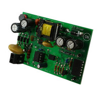
EVAL BOARD FOR NCP1028LEDG
Manufacturer
ON Semiconductor
Specifications of NCP1028LEDGEVB
Design Resources
NCP1028LEDGEVB BOM CP1028LEDGEVB Gerber Files NCP1028LED EVB Schematic
Current - Output / Channel
720mA
Outputs And Type
1, Isolated
Voltage - Output
18V
Voltage - Input
90 ~ 265VAC
Utilized Ic / Part
NCP1028
Core Chip
NCP1028
Topology
Flyback
No. Of Outputs
1
Output Current
720mA
Output Voltage
18V
Development Tool Type
Hardware - Eval/Demo Board
Leaded Process Compatible
Yes
Mcu Supported Families
NCP1028
Rohs Compliant
Yes
Lead Free Status / RoHS Status
Lead free / RoHS Compliant
Features
-
Lead Free Status / Rohs Status
Lead free / RoHS Compliant
For Use With/related Products
NCP1028LEDG
Other names
NCP1028LEDGEVBOS


Fault Condition – Low Input Voltage
protect the power supply in case of low input voltage
conditions. Figure 29 shows how internally the NCP1028
monitors the voltage image of the bulk capacitor. Below a
given level, the controller blocks the driving pulses, above
it, it authorizes them. The internal circuitry, depicted by
it becomes possible to select the turn-on and turn-off levels via a few lines of algebra.
IBO is Off
IBO is On
configuration with an offset current source.
Rupper
Rlower
The NCP1028 includes a brown-out circuitry able to
To the contrary, when the internal BO signal is high, the IBO source is activated and creates an hysteresis. As a result,
We can now extract
If we decide to turn-on our converter for Vbulk1 equals 100 V and turn it off for Vbulk2 equals 70 V, then we obtain:
R
R
upper
lower
Figure 29a. The internal brown-out
Vbulk
= 3.0 MW
= 18 kW
BO
IBO
V
DD
R
lower
ON/OFF
+
V()) + V bulk2
VBO
from Equation 1 and plug it into Equation 2, then solve for
+
-
R lower + VBO
BO
V()) + V bulk1
R upper + R lower
R lower ) R upper
16.0
12.0
8.00
4.00
0
http://onsemi.com
R lower
80.0
40.0
160
120
0
Figure 29.
1
NCP1028
vin
Figure 29b. Simulation results for 100/70 ON/OFF levels.
Vbulk = 100 V
IBO
20.0u
16
2
R lower ) R upper
vcmp
V bulk1 -V bulk2
Figure 29a, offers a way to observe the high-voltage (HV)
rail. A resistive divider made of
a portion of the HV rail on pin 3. Below the turn-on level,
the 10 mA current source IBO is off. Therefore, the turn-on
level solely depends on the division ratio brought by the
resistive divider.
) IBO
V bulk1 -VBO
(V bulk1 -VBO)
R lower
VBO
60.0u
R lower
R lower ) R upper
Time in Seconds
R upper
100u
R
upper
R
:
upper
140u
and
Vbulk = 70 V
R
lower
180u
, brings
(eq. 1)
(eq. 2)
2 1
Related parts for NCP1028LEDGEVB
Image
Part Number
Description
Manufacturer
Datasheet
Request
R

Part Number:
Description:
Low Dropout Linear Regulator Controller
Manufacturer:
ON Semiconductor
Datasheet:

Part Number:
Description:
EVAL BOARD FOR NCP102MBG
Manufacturer:
ON Semiconductor
Datasheet:
Part Number:
Description:
ON Semiconductor [VOLTAGE REGULATOR]
Manufacturer:
ON Semiconductor
Datasheet:
Part Number:
Description:
357-036-542-201 CARDEDGE 36POS DL .156 BLK LOPRO
Manufacturer:
ON Semiconductor
Datasheet:
Part Number:
Description:
357-036-542-201 CARDEDGE 36POS DL .156 BLK LOPRO
Manufacturer:
ON Semiconductor
Datasheet:
Part Number:
Description:
357-036-542-201 CARDEDGE 36POS DL .156 BLK LOPRO
Manufacturer:
ON Semiconductor
Datasheet:
Part Number:
Description:
357-036-542-201 CARDEDGE 36POS DL .156 BLK LOPRO
Manufacturer:
ON Semiconductor
Datasheet:
Part Number:
Description:
357-036-542-201 CARDEDGE 36POS DL .156 BLK LOPRO
Manufacturer:
ON Semiconductor
Datasheet:
Part Number:
Description:
357-036-542-201 CARDEDGE 36POS DL .156 BLK LOPRO
Manufacturer:
ON Semiconductor
Datasheet:
Part Number:
Description:
357-036-542-201 CARDEDGE 36POS DL .156 BLK LOPRO
Manufacturer:
ON Semiconductor
Datasheet:
Part Number:
Description:
357-036-542-201 CARDEDGE 36POS DL .156 BLK LOPRO
Manufacturer:
ON Semiconductor
Datasheet:
Part Number:
Description:
357-036-542-201 CARDEDGE 36POS DL .156 BLK LOPRO
Manufacturer:
ON Semiconductor
Datasheet:
Part Number:
Description:
357-036-542-201 CARDEDGE 36POS DL .156 BLK LOPRO
Manufacturer:
ON Semiconductor
Datasheet:
Part Number:
Description:
Manufacturer:
ON Semiconductor
Datasheet: