SI3461-KIT Silicon Laboratories Inc, SI3461-KIT Datasheet - Page 7
SI3461-KIT
Manufacturer Part Number
SI3461-KIT
Description
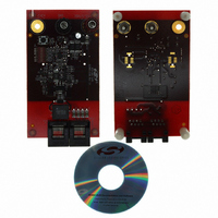
BOARD EVAL FOR SI3461
Manufacturer
Silicon Laboratories Inc
Type
Controllers & Processorsr
Specifications of SI3461-KIT
Main Purpose
Special Purpose DC/DC, Power Over Ethernet
Board Type
Fully Populated
Utilized Ic / Part
Si3461
Ethernet Connection Type
10/100 Base-T, IEEE 802.3
Interface Type
Ethernet
Operating Voltage
12 V to 15 V
Operating Current
10 mA
Product
Modules
For Use With/related Products
Si3460
Lead Free Status / RoHS Status
Lead free / RoHS non-compliant
Current - Output
-
Voltage - Output
-
Voltage - Input
-
Power - Output
-
Frequency - Switching
-
Outputs And Type
-
Regulator Topology
-
Lead Free Status / Rohs Status
Lead free / RoHS Compliant
Other names
336-1843


Si3460-EVB
5.6. Power-Up
After successful classification, the Si3460 is configured to produce a nominal –50 V output voltage. The overload
current limits are set based on the classification voltage on the STATUS pin at powerup. Refer to Table 1 of the
Si3460 data sheet for more information.
For output current durations lasting longer than 60 ms, the power is removed if the maximum power level of either
4, 7, or 15.4 W is exceeded by approximately 10%, as determined by the operating mode detected at start up (refer
to Section “5.1. Initialization and Operating Mode Configuration”). In the event of an output short circuit, the Si3460
will immediately disconnect so as to prevent shorting the input supply through D8 and L1.
The Si3460 can be configured to operate in a mode where it will automatically retry detection and power up after an
overload. Alternatively, the Si3460 can be programmed to signal an error condition has occurred, in which case the
user must assert RST (e.g., by pushing the reset switch on the Si3460-EVB) to start a new detection and power up
cycle.
As set by the initial voltage on the STATUS pin at powerup, the Si3460 will then automatically resume the detection
process for "automatic restart configuration" unless the Si3460 is configured in a "restart after a RESET condition"
mode and a fault condition is detected; in that case, the LED will flash rapidly, and the detection process will
automatically start again after 2.2 seconds. Power will not be provided until an open-circuit condition is detected.
Once the Si3460-EVB detects an open-circuit condition (normally by removing the Ethernet cable from the
Si3460-EVB’s RJ-45 jack labelled “To PD”), the detection process begins, the status LED blinks at the rate of 3
times per second, and the Si3460 is then allowed to go into classification and powerup mode if a valid PD signature
resistance is detected. The relevant waveform is shown in Figure 6 on page 12.
5.7. Disconnect (Power Removal)
The Si3460 supports a robust disconnect algorithm. If the current drops below 5 mA for between 300 and 400 ms,
the power is removed. If the output current then exceeds 10 mA for at least 60 ms, the power is not removed. The
Si3460 will continue to provide power unless a disconnect or overload condition is sensed. The only other way to
force the Si3460 to disconnect power is by doing a reset. The relevant waveform is shown in Figure 7 on page 12.
5.8. Current Limit Control
The Si3460's overcurrent trip point is determined by the output power set during the classification stage power
granting process. If the output current exceeds the threshold, a timer counts up towards a time-out of 60 ms. If the
current drops below the set threshold, the timer counts down towards zero at 1/16th the rate. If the timer reaches
60 ms, an overcurrent fault is declared, and the channel is shut down by turning off the dc-dc converter clock and
then turning off the FET M1. After an overcurrent fault event, the LED will flash rapidly.
As set by the initial voltage on the STATUS pin at powerup, the Si3460 will then automatically resume the detection
process for "automatic restart configuration" unless the Si3460 is configured in a "restart after a RESET condition"
mode and a fault condition is detected; in that case, the LED will flash rapidly, and the detection process will
automatically start again after 2.2 seconds. Power will not be provided until an open-circuit condition is detected.
Once the Si3460-EVB detects an open-circuit condition (normally by removing the Ethernet cable from the
Si3460-EVB’s RJ-45 jack labelled “To PD”), the detection process begins, the status LED blinks at the rate of 3
times per second, and the Si3460 is then allowed to go into classification and powerup mode if a valid PD signature
resistance is detected.
5.9. UVLO
The Si3460-EVB reference design is optimized for 12 to 15 V nominal input voltages* (11 V minimum to 16 V
maximum). If the input voltage drops below 10 V in detection mode or if the output voltage drops below 10 V in
classification or power up mode, a UVLO condition is declared which generates the error condition (LED flashing
rapidly). An under-voltage event is a fault condition which is reported through the status LED as a rapid blinking of
10 flashes per second. The UVLO condition is continuously monitored in all operating states.
*Note: Some MOSFET gate drivers operate at a maximum supply voltage of 14 V (for example, TPS2828). In that case, the
input voltage must be limited to a maximum of 12 V.
Rev. 1.1
7
Related parts for SI3461-KIT
Image
Part Number
Description
Manufacturer
Datasheet
Request
R

Part Number:
Description:
QFN 11/I°/SINGLE-PORT POE / POE+ PSE INTERFACE
Manufacturer:
Silicon Laboratories Inc
Part Number:
Description:
IC POWER MANAGEMENT CTLR 11VQFN
Manufacturer:
Silicon Laboratories Inc
Datasheet:
Part Number:
Description:
IC POWER MANAGEMENT CTLR 11VQFN
Manufacturer:
Silicon Laboratories Inc
Datasheet:
Part Number:
Description:
IC POWER MANAGEMENT CTLR 11VQFN
Manufacturer:
Silicon Laboratories Inc
Datasheet:
Part Number:
Description:
SMD/C°/SINGLE-ENDED OUTPUT SILICON OSCILLATOR
Manufacturer:
Silicon Laboratories Inc
Part Number:
Description:
Manufacturer:
Silicon Laboratories Inc
Datasheet:
Part Number:
Description:
N/A N/A/SI4010 AES KEYFOB DEMO WITH LCD RX
Manufacturer:
Silicon Laboratories Inc
Datasheet:
Part Number:
Description:
N/A N/A/SI4010 SIMPLIFIED KEY FOB DEMO WITH LED RX
Manufacturer:
Silicon Laboratories Inc
Datasheet:
Part Number:
Description:
N/A/-40 TO 85 OC/EZLINK MODULE; F930/4432 HIGH BAND (REV E/B1)
Manufacturer:
Silicon Laboratories Inc
Part Number:
Description:
EZLink Module; F930/4432 Low Band (rev e/B1)
Manufacturer:
Silicon Laboratories Inc
Part Number:
Description:
I°/4460 10 DBM RADIO TEST CARD 434 MHZ
Manufacturer:
Silicon Laboratories Inc
Part Number:
Description:
I°/4461 14 DBM RADIO TEST CARD 868 MHZ
Manufacturer:
Silicon Laboratories Inc
Part Number:
Description:
I°/4463 20 DBM RFSWITCH RADIO TEST CARD 460 MHZ
Manufacturer:
Silicon Laboratories Inc
Part Number:
Description:
I°/4463 20 DBM RADIO TEST CARD 868 MHZ
Manufacturer:
Silicon Laboratories Inc