SI3461-KIT Silicon Laboratories Inc, SI3461-KIT Datasheet - Page 23
SI3461-KIT
Manufacturer Part Number
SI3461-KIT
Description
BOARD EVAL FOR SI3461
Manufacturer
Silicon Laboratories Inc
Type
Controllers & Processorsr
Specifications of SI3461-KIT
Main Purpose
Special Purpose DC/DC, Power Over Ethernet
Board Type
Fully Populated
Utilized Ic / Part
Si3461
Ethernet Connection Type
10/100 Base-T, IEEE 802.3
Interface Type
Ethernet
Operating Voltage
12 V to 15 V
Operating Current
10 mA
Product
Modules
For Use With/related Products
Si3460
Lead Free Status / RoHS Status
Lead free / RoHS non-compliant
Current - Output
-
Voltage - Output
-
Voltage - Input
-
Power - Output
-
Frequency - Switching
-
Outputs And Type
-
Regulator Topology
-
Lead Free Status / Rohs Status
Lead free / RoHS Compliant
Other names
336-1843


Si3460-EVB
11. Operating the Si3460-EVB
The Si3460-EVB itself is very simple to use. Only a basic 12 or 15 V dc power source (i.e., a wall wart) with at least
an 18 W rating is needed for connection to J4. The Si3460 will automatically power up, detect the operational
modes (midspan/endpoint, classification power level, and restart mode), and then begin the detection process,
during which the LED flashes at 3 times per second.
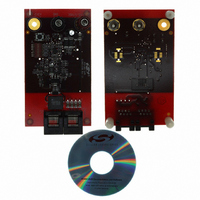
Figure 17. Si3460-EVB
To test the Si3460-EVB in a PoE environment, many commercial PDs are available, such as Wireless Access
Points (WAPs), Voice over IP phones (VoIP), and IP-based security cameras. Any of these can be connected to the
Si3460-EVB to receive PSE power while exchanging Ethernet traffic.
Another PD option is to use the Si3460-EVB with one of the Si3400/01 evaluation boards. If a Si3400 EVB is used
with the Si3460-EVB, the S3400 EVB should be configured to present a minimum load of > 0.25 W to ensure that it
draws at least 10 mA to comply with the IEEE standard.
When the Si3460 is applying power to a valid PD, the LED is continuously lit. After an error condition (e.g., an
UVLO or short-circuit event) is detected, the LED flashes at 10 times per second, or until a reset is asserted, or
when an open circuit is detected as determined by the operating mode of the Si3460.
Resistors R23, R25, and the programming header J6 are used for development purposes only. The Si3460 is not
user programmable, and it is not recommended these components be included in actual layouts (short R23 and
R25, and remove J6).
The Si3460 mode is set by resistors R28 and R30. Placeholder values of 10 k are shown in the schematics. To
keep the voltage level at the transistor base accurate, it is recommended that the parallel resistor combination
setting the pin voltage be less than 2 k. It is expected that most applications will support full power in either a
midspan or endpoint application and enable automatic reset after an overload.
The reference board is shipped configured for midspan power injection with full power support and automatic retry
after a fault. Resistors R28 and R30 may be replaced to support other modes of operation. See Section "5.1.
Initialization and Operating Mode Configuration" on page 5 for more information.
Rev. 1.1
23
Related parts for SI3461-KIT
Image
Part Number
Description
Manufacturer
Datasheet
Request
R

Part Number:
Description:
QFN 11/I°/SINGLE-PORT POE / POE+ PSE INTERFACE
Manufacturer:
Silicon Laboratories Inc
Part Number:
Description:
IC POWER MANAGEMENT CTLR 11VQFN
Manufacturer:
Silicon Laboratories Inc
Datasheet:
Part Number:
Description:
IC POWER MANAGEMENT CTLR 11VQFN
Manufacturer:
Silicon Laboratories Inc
Datasheet:
Part Number:
Description:
IC POWER MANAGEMENT CTLR 11VQFN
Manufacturer:
Silicon Laboratories Inc
Datasheet:
Part Number:
Description:
SMD/C°/SINGLE-ENDED OUTPUT SILICON OSCILLATOR
Manufacturer:
Silicon Laboratories Inc
Part Number:
Description:
Manufacturer:
Silicon Laboratories Inc
Datasheet:
Part Number:
Description:
N/A N/A/SI4010 AES KEYFOB DEMO WITH LCD RX
Manufacturer:
Silicon Laboratories Inc
Datasheet:
Part Number:
Description:
N/A N/A/SI4010 SIMPLIFIED KEY FOB DEMO WITH LED RX
Manufacturer:
Silicon Laboratories Inc
Datasheet:
Part Number:
Description:
N/A/-40 TO 85 OC/EZLINK MODULE; F930/4432 HIGH BAND (REV E/B1)
Manufacturer:
Silicon Laboratories Inc
Part Number:
Description:
EZLink Module; F930/4432 Low Band (rev e/B1)
Manufacturer:
Silicon Laboratories Inc
Part Number:
Description:
I°/4460 10 DBM RADIO TEST CARD 434 MHZ
Manufacturer:
Silicon Laboratories Inc
Part Number:
Description:
I°/4461 14 DBM RADIO TEST CARD 868 MHZ
Manufacturer:
Silicon Laboratories Inc
Part Number:
Description:
I°/4463 20 DBM RFSWITCH RADIO TEST CARD 460 MHZ
Manufacturer:
Silicon Laboratories Inc
Part Number:
Description:
I°/4463 20 DBM RADIO TEST CARD 868 MHZ
Manufacturer:
Silicon Laboratories Inc