SI3461-KIT Silicon Laboratories Inc, SI3461-KIT Datasheet - Page 6
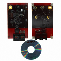
SI3461-KIT
Manufacturer Part Number
SI3461-KIT
Description
BOARD EVAL FOR SI3461
Manufacturer
Silicon Laboratories Inc
Type
Controllers & Processorsr
Specifications of SI3461-KIT
Main Purpose
Special Purpose DC/DC, Power Over Ethernet
Board Type
Fully Populated
Utilized Ic / Part
Si3461
Ethernet Connection Type
10/100 Base-T, IEEE 802.3
Interface Type
Ethernet
Operating Voltage
12 V to 15 V
Operating Current
10 mA
Product
Modules
For Use With/related Products
Si3460
Lead Free Status / RoHS Status
Lead free / RoHS non-compliant
Current - Output
-
Voltage - Output
-
Voltage - Input
-
Power - Output
-
Frequency - Switching
-
Outputs And Type
-
Regulator Topology
-
Lead Free Status / Rohs Status
Lead free / RoHS Compliant
Other names
336-1843


Si3460-EVB
5.2. CTRL1 and CTRL2
These two pins are the output of two 96 kHz 8-bit pulse width modulators. The output of these pins is averaged
using R15, R29, and C5 to produce a dc level across C5 that is controllable with 16-bit resolution. This dc voltage
is used to control both the detection process and the pulse width modulator for the dc-dc converter.
5.3. Detection
During the detection phase, the pass transistor M2 is held off by driving the GATE pin high. The 250 kHz clock for
the PWM circuit is held low, forcing the switcher FET M1 off.
In the detect state, the output voltage is determined by the output of U18A feeding the resistive bridge R1, R2, and
R3. The PD at the other end of a cable forms the fourth leg of the bridge. The return path to Vee is through D8 and
L1. The bridge null is read through amplifier U18B, which is fed to the Si3460 pin DETA.
The output of U18A is controlled by the CTRL1 and CTRL2 pins as noted earlier. For most of the detection cycle,
the CTRL pins are held high which forces U18A low, producing no output. The bridge voltage is varied to force
IEEE compliant detection voltages of approximately 4.5 and 7.5 V across the bridge with 20 ms delay and robust
three-point detection algorithm at 4.5, 7.5, and back to 4.5 V. To robustly insure that the PD has a valid resistive
signature, the bridge null is checked as the voltage increases and then checked again as the voltage decreases.
Relevant waveforms are shown in Figure 4 and Figure 5 on page 11.
5.4. PWM
In order to apply power to the load, M2 is turned on by driving the Si3460's GATE pin high. At the same time, the
PWM circuitry is enabled by turning on the 250 kHz clock (250 kHz pin). The 250 kHz square wave is converted to
a triangular shape by the filter R14 and C6. The dc level set by CTRL1 and CTRL2 is used to control the PWM
comparator U19B that drives the switcher FET through gate driver U3.
The output voltage is sensed through resistor divider R43 and R44, and the output current is sensed through
resistor R4. The Si3460 integrates an A/D that measures these quantities and varies the CTRL1 and CTRL2 duty
cycle to regulate the output current and voltage as desired.
5.5. Classification
For classification, M2 is turned on and the PWM is enabled. The Si3460 is programmed to perform classification at
18 V output voltage, with a current limit of between 50 and 100 mA. Classification is performed after allowing 20 ms
of settling time.
Since the Si3460-EVB is designed for a single port PSE application, the classification information is only used to
determine if the load is in the range that is supported, according to the mode of the Si3460 determined at power up
(refer to STATUS pin in Section “5.1. Initialization and Operating Mode Configuration”).
If the measured classification level is not in the supported range, an error is declared and the Si3460 will either time
out and retry and wait for a reset as determined by the power up mode of operation. Relevant waveforms are
shown in Figure 5 on page 11 and Figure 6 on page 12. If the class level is in the supported range, the Si3460
proceeds to powerup.
6
Class 1 or Class 2
Classification
Class 1 only
Full power
Mode
PSE Minimum
Output Power
15.4 W
4 W
7 W
Only apply power if the current
Table 3. Classification Levels
Only apply full power if the
21 mA (class 1 or class 2)
current is between 8 and
is between 8 and 13 mA
Always apply full power
Action Performed
(class 1)
Rev. 1.1
Threshold I
Overload Current
400 mA
180 mA
98 mA
CUT
(Max)
Overload Current
Limit I
450 mA
450 mA
450 mA
LIM
(Max)
Related parts for SI3461-KIT
Image
Part Number
Description
Manufacturer
Datasheet
Request
R

Part Number:
Description:
QFN 11/I°/SINGLE-PORT POE / POE+ PSE INTERFACE
Manufacturer:
Silicon Laboratories Inc
Part Number:
Description:
IC POWER MANAGEMENT CTLR 11VQFN
Manufacturer:
Silicon Laboratories Inc
Datasheet:
Part Number:
Description:
IC POWER MANAGEMENT CTLR 11VQFN
Manufacturer:
Silicon Laboratories Inc
Datasheet:
Part Number:
Description:
IC POWER MANAGEMENT CTLR 11VQFN
Manufacturer:
Silicon Laboratories Inc
Datasheet:
Part Number:
Description:
SMD/C°/SINGLE-ENDED OUTPUT SILICON OSCILLATOR
Manufacturer:
Silicon Laboratories Inc
Part Number:
Description:
Manufacturer:
Silicon Laboratories Inc
Datasheet:
Part Number:
Description:
N/A N/A/SI4010 AES KEYFOB DEMO WITH LCD RX
Manufacturer:
Silicon Laboratories Inc
Datasheet:
Part Number:
Description:
N/A N/A/SI4010 SIMPLIFIED KEY FOB DEMO WITH LED RX
Manufacturer:
Silicon Laboratories Inc
Datasheet:
Part Number:
Description:
N/A/-40 TO 85 OC/EZLINK MODULE; F930/4432 HIGH BAND (REV E/B1)
Manufacturer:
Silicon Laboratories Inc
Part Number:
Description:
EZLink Module; F930/4432 Low Band (rev e/B1)
Manufacturer:
Silicon Laboratories Inc
Part Number:
Description:
I°/4460 10 DBM RADIO TEST CARD 434 MHZ
Manufacturer:
Silicon Laboratories Inc
Part Number:
Description:
I°/4461 14 DBM RADIO TEST CARD 868 MHZ
Manufacturer:
Silicon Laboratories Inc
Part Number:
Description:
I°/4463 20 DBM RFSWITCH RADIO TEST CARD 460 MHZ
Manufacturer:
Silicon Laboratories Inc
Part Number:
Description:
I°/4463 20 DBM RADIO TEST CARD 868 MHZ
Manufacturer:
Silicon Laboratories Inc