DM300023 Microchip Technology, DM300023 Datasheet - Page 219
DM300023
Manufacturer Part Number
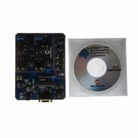
DM300023
Description
KIT DEMO DSPICDEM SMPS BUCK
Manufacturer
Microchip Technology
Series
dsPIC™r
Datasheets
1.AC164335.pdf
(286 pages)
2.DM300023.pdf
(22 pages)
3.DM300023.pdf
(18 pages)
4.DM300023.pdf
(50 pages)
5.DM300023.pdf
(16 pages)
Specifications of DM300023
Main Purpose
DC/DC, Step Down
Outputs And Type
2, Non-Isolated
Voltage - Input
7 ~ 15V
Regulator Topology
Buck
Board Type
Fully Populated
Utilized Ic / Part
dsPIC30F2020
Processor To Be Evaluated
dsPIC30F202x/1010
Interface Type
RS-232
Lead Free Status / RoHS Status
Lead free / RoHS Compliant
Current - Output
-
Voltage - Output
-
Power - Output
-
Frequency - Switching
-
Lead Free Status / Rohs Status
Lead free / RoHS Compliant
Available stocks
Company
Part Number
Manufacturer
Quantity
Price
Company:

Part Number:
DM300023
Manufacturer:
Microchip Technology
Quantity:
135
Company:
Part Number:
DM300023
Manufacturer:
MICROCHIP
Quantity:
12 000


TABLE 18-7:
18.11 In-Circuit Debugger
When MPLAB
in-circuit debugging functionality is enabled. This func-
tion allows simple debugging functions when used with
MPLAB IDE. When the device has this feature enabled,
some of the resources are not available for general
use. These resources include the first 80 bytes of data
RAM and two I/O pins.
One of four pairs of Debug I/O pins may be selected by
the user using configuration options in MPLAB IDE.
These pin pairs are named EMUD/EMUC, EMUD1/
EMUC1 and EMUD2/EMUC2.
In each case, the selected EMUD pin is the Emulation/
Debug Data line, and the EMUC pin is the Emulation/
Debug Clock line. These pins will interface to the
MPLAB ICD 2 module available from Microchip. The
selected pair of Debug I/O pins is used by
MPLAB ICD 2 to send commands and receive
responses, as well as to send and receive data. To use
the in-circuit debugging function of the device, the
design must implement ICSP connections to MCLR,
V
EMUDx/EMUCx pin pair.
© 2006 Microchip Technology Inc.
FWDTEN
WWDTEN
WDTPRE
WDTPOST<3:0>
FPWRT<2:0>
DD
, V
Bit Field
SS
, PGC, PGD and the selected
®
ICD 2 is selected as a debugger, the
FWDT AND FPOR BIT DESCRIPTIONS FOR dsPIC30F1010/202X
Register
FWDT
FWDT
FWDT
FWDT
FPOR
Watchdog Timer Enable bit
1 = Watchdog Timer always enabled. (LPRC oscillator cannot be dis-
0 = Watchdog Timer enabled/disabled by user software (LPRC can be
Watchdog Timer Window Enable bit
1 = Watchdog Timer in Non-Window mode
0 = Watchdog Timer in Window mode
Watchdog Timer Prescaler bit
1 = 1:128
0 = 1:32
Watchdog Timer Postscaler bits
1111 = 1:32, 768
1110 = 1:16, 384
.
.
.
0001 = 1:2
0000 = 1:1
Power-on Reset Timer Value Select bits
111 = PWRT = 128 ms
110 = PWRT = 64 ms
101 = PWRT = 32 ms
100 = PWRT = 16 ms
011 = PWRT = 8 ms
010 = PWRT = 4 ms
001 = PWRT = 2 ms
000 = PWRT = Disabled
abled. Clearing the SWDTEN bit in the RCON register will have no
effect.)
disabled by clearing the SWDTEN bit in the RCON register)
Preliminary
This gives rise to two possibilities:
1.
2.
dsPIC30F1010/202X
If EMUD/EMUC is selected as the debug I/O pin
pair, then only a 5-pin interface is required, as
the EMUD and EMUC pin functions are multi-
plexed with the PGD and PGC pin functions in
all dsPIC30F devices.
If
selected as the debug I/O pin pair, then a 7-pin
interface is required, as the EMUDx/EMUCx pin
functions (x = 1 or 2) are not multiplexed with the
PGD and PGC pin functions.
EMUD1/EMUC1
Description
or
EMUD2/EMUC2
DS70178C-page 217
is
Related parts for DM300023
Image
Part Number
Description
Manufacturer
Datasheet
Request
R

Part Number:
Description:
Manufacturer:
Microchip Technology Inc.
Datasheet:
Part Number:
Description:
Manufacturer:
Microchip Technology Inc.
Datasheet:
Part Number:
Description:
Manufacturer:
Microchip Technology Inc.
Datasheet:
Part Number:
Description:
Manufacturer:
Microchip Technology Inc.
Datasheet:
Part Number:
Description:
Manufacturer:
Microchip Technology Inc.
Datasheet:
Part Number:
Description:
Manufacturer:
Microchip Technology Inc.
Datasheet:
Part Number:
Description:
Manufacturer:
Microchip Technology Inc.
Datasheet:
Part Number:
Description:
Manufacturer:
Microchip Technology Inc.
Datasheet: