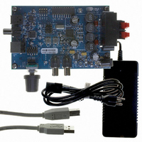
CRD4525-Q1 Cirrus Logic Inc, CRD4525-Q1 Datasheet - Page 95

CRD4525-Q1
Manufacturer Part Number
CRD4525-Q1
Description
REFERENCE BOARD FOR CS4525 PWM
Manufacturer
Cirrus Logic Inc
Series
Popguard®r
Specifications of CRD4525-Q1
Amplifier Type
Class D
Output Type
2-Channel (Stereo)
Max Output Power X Channels @ Load
15W x 2 @ 8 Ohm
Voltage - Supply
12 V ~ 18 V
Operating Temperature
0°C ~ 70°C
Board Type
Fully Populated
Utilized Ic / Part
CS4525
Lead Free Status / RoHS Status
Contains lead / RoHS non-compliant
Other names
598-1586
DS726PP3
10.PARAMETER DEFINITIONS
Dynamic Range (DYR)
Total Harmonic Distortion + Noise (THD+N)
Frequency Response
Interchannel Isolation
Interchannel Gain Mismatch
Gain Drift
Fs
Resolution
SRC
11.REFERENCES
1. Cirrus Logic, “AN18: Layout and Design Rules for Data Converters and Other Mixed Signal Devices,”
2. Cirrus Logic, “AN22: Overview of Digital Audio Interface Data Structures, Version 2.0”, February 1998.; A
3. Philips Semiconductor, “The I²C-Bus Specification: Version 2,” Dec. 1998.
The ratio of the rms value of the signal to the rms sum of all other spectral components over the specified
bandwidth, typically 20 Hz to 20 kHz. Dynamic Range is a signal-to-noise ratio measurement over the spec-
ified band width made with a -60 dBFS signal. 60 dB is then added to the resulting measurement to refer
the measurement to full-scale. This technique ensures that the distortion components are below the noise
level and do not effect the measurement. This measurement technique has been accepted by the Audio
Engineering Society, AES17-1991, and the Electronic Industries Association of Japan, EIAJ CP-307. Ex-
pressed in decibels.
The ratio of the rms value of the signal to the rms sum of all other spectral components over the specified
band width (typically 10 Hz to 20 kHz), including distortion components. Expressed in decibels. Measured
as suggested in AES17-1991 Annex A.
FR is the deviation in signal level verses frequency. The 0 dB reference point is 1 kHz. The amplitude cor-
ner, Ac, lists the maximum deviation in amplitude above and below the 1 kHz reference point. The listed
minimum and maximum frequencies are guaranteed to be within the Ac from minimum frequency to maxi-
mum frequency inclusive.
A measure of crosstalk between the left and right channels. Measured for each channel at the converter's
output with no signal to the input under test and a full-scale signal applied to the other channel. Units in deci-
bels.
The gain difference between left and right channels. Units in decibels.
The change in gain value with temperature. Units in ppm/°C.
Sampling Frequency.
The number of bits in a serial audio data word.
Sample Rate Converter. Converts data derived at one sample rate to a differing sample rate.
Version 6.0, February 1998.
useful tutorial on digital audio specifications.
http://www.semiconductors.philips.com
CS4525
95


