CRD4525-Q1 Cirrus Logic Inc, CRD4525-Q1 Datasheet - Page 3
CRD4525-Q1
Manufacturer Part Number
CRD4525-Q1
Description
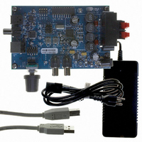
REFERENCE BOARD FOR CS4525 PWM
Manufacturer
Cirrus Logic Inc
Series
Popguard®r
Specifications of CRD4525-Q1
Amplifier Type
Class D
Output Type
2-Channel (Stereo)
Max Output Power X Channels @ Load
15W x 2 @ 8 Ohm
Voltage - Supply
12 V ~ 18 V
Operating Temperature
0°C ~ 70°C
Board Type
Fully Populated
Utilized Ic / Part
CS4525
Lead Free Status / RoHS Status
Contains lead / RoHS non-compliant
Other names
598-1586


DS726PP3
TABLE OF CONTENTS
1. PIN DESCRIPTIONS - SOFTWARE MODE .......................................................................................... 8
2. PIN DESCRIPTIONS - HARDWARE MODE ....................................................................................... 10
3. TYPICAL CONNECTION DIAGRAMS ................................................................................................. 13
4. TYPICAL SYSTEM CONFIGURATION DIAGRAMS ........................................................................... 15
5. CHARACTERISTICS AND SPECIFICATIONS .................................................................................... 18
6. APPLICATIONS ................................................................................................................................... 26
2.1 Digital I/O Pin Characteristics ........................................................................................................ 12
6.1 Software Mode ............................................................................................................................... 26
6.2 Hardware Mode ............................................................................................................................. 54
6.1.1 System Clocking ................................................................................................................... 26
6.1.2 Power-Up and Power-Down ................................................................................................. 28
6.1.3 Input Source Selection .......................................................................................................... 29
6.1.4 Digital Sound Processing ...................................................................................................... 29
6.1.5 Auxiliary Serial Output .......................................................................................................... 43
6.1.6 Serial Audio Delay & Warning Input Port .............................................................................. 44
6.1.7 Powered PWM Outputs ........................................................................................................ 45
6.1.8 Logic-Level PWM Outputs .................................................................................................... 46
6.1.9 PWM Modulator Configuration .............................................................................................. 50
6.1.10 Headphone Detection & Hardware Mute Input ................................................................... 51
6.1.11 Interrupt Reporting .............................................................................................................. 53
6.1.12 Automatic Power Stage Shut-Down ................................................................................... 53
6.2.1 System Clocking ................................................................................................................... 54
6.2.2 Power-Up and Power-Down ................................................................................................. 54
6.1.1.1 SYS_CLK Input Clock Mode .................................................................................... 26
6.1.1.2 Crystal Oscillator Mode ............................................................................................ 27
6.1.2.1 Power-Up Sequence ................................................................................................ 28
6.1.2.2 Power-Down Sequence ............................................................................................ 28
6.1.4.1 Pre-Scaler ................................................................................................................. 30
6.1.4.2 Digital Signal Processing High-Pass Filter ............................................................... 30
6.1.4.3 Channel Mixer .......................................................................................................... 30
6.1.4.4 De-Emphasis ............................................................................................................ 31
6.1.4.5 Tone Control ............................................................................................................. 31
6.1.4.6 Parametric EQ .......................................................................................................... 33
6.1.4.7 Adaptive Loudness Compensation ........................................................................... 34
6.1.4.8 Bass Management .................................................................................................... 35
6.1.4.9 Volume and Muting Control ...................................................................................... 36
6.1.4.10 Peak Signal Limiter ................................................................................................. 37
6.1.4.11 Thermal Limiter ....................................................................................................... 39
6.1.4.12 Thermal Foldback ................................................................................................... 40
6.1.4.13 2-Way Crossover & Sensitivity Control ................................................................... 42
6.1.6.1 Serial Audio Delay Interface ..................................................................................... 44
6.1.6.2 External Warning Input Port ..................................................................................... 44
6.1.7.1 Output Channel Configurations ................................................................................ 45
6.1.7.2 PWM Popguard Transient Control ............................................................................ 45
6.1.8.1 Recommended PWM_SIG Power-Up Sequence for an External PWM Amplifier .... 47
6.1.8.2 Recommended PWM_SIG Power-Down Sequence for an External PWM Amplifier 47
6.1.8.3 Recommended PWM_SIG Power-Up Sequence for Headphone & Line-Out .......... 48
6.1.8.4 Recommended PWM_SIG Power-Down Sequence for Headphone & Line-Out ..... 48
6.1.8.5 PWM_SIG Logic-Level Output Configurations ......................................................... 49
6.1.9.1 PWM Channel Delay ................................................................................................ 50
6.1.9.2 PWM AM Frequency Shift ........................................................................................ 51
6.2.2.1 Power-Up Sequence ................................................................................................ 54
CS4525
3
Related parts for CRD4525-Q1
Image
Part Number
Description
Manufacturer
Datasheet
Request
R

Part Number:
Description:
Development Kit
Manufacturer:
Cirrus Logic Inc
Datasheet:
Part Number:
Description:
Development Kit
Manufacturer:
Cirrus Logic Inc
Datasheet:


Part Number:
Description:
High-efficiency PFC + Fluorescent Lamp Driver Reference Design
Manufacturer:
Cirrus Logic Inc
Datasheet:
Part Number:
Description:
Development Kit
Manufacturer:
Cirrus Logic Inc
Datasheet:
Part Number:
Description:
Development Kit
Manufacturer:
Cirrus Logic Inc
Datasheet:

Part Number:
Description:
Development Kit
Manufacturer:
Cirrus Logic Inc
Datasheet:
Part Number:
Description:
Development Kit
Manufacturer:
Cirrus Logic Inc
Datasheet:
Part Number:
Description:
Development Kit
Manufacturer:
Cirrus Logic Inc
Datasheet:
Part Number:
Description:
Audio Modules & Development Tools EvalBd 30W Qd Hlf- Brdg Dig Amp Pwr Stg
Manufacturer:
Cirrus Logic Inc
Datasheet:

Part Number:
Description:
EVALUATION BOARD FOR CS8427
Manufacturer:
Cirrus Logic Inc
Datasheet:

Part Number:
Description:
BOARD EVAL FOR CS8416 RCVR
Manufacturer:
Cirrus Logic Inc
Datasheet:

Part Number:
Description:
EVALUATION BOARD FOR CS8420
Manufacturer:
Cirrus Logic Inc
Datasheet:

Part Number:
Description:
KIT DEVELOPMENT EP9315 ARM9
Manufacturer:
Cirrus Logic Inc
Datasheet: