CRD4525-Q1 Cirrus Logic Inc, CRD4525-Q1 Datasheet - Page 20
CRD4525-Q1
Manufacturer Part Number
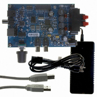
CRD4525-Q1
Description
REFERENCE BOARD FOR CS4525 PWM
Manufacturer
Cirrus Logic Inc
Series
Popguard®r
Specifications of CRD4525-Q1
Amplifier Type
Class D
Output Type
2-Channel (Stereo)
Max Output Power X Channels @ Load
15W x 2 @ 8 Ohm
Voltage - Supply
12 V ~ 18 V
Operating Temperature
0°C ~ 70°C
Board Type
Fully Populated
Utilized Ic / Part
CS4525
Lead Free Status / RoHS Status
Contains lead / RoHS non-compliant
Other names
598-1586


20
PWM POWER OUTPUT CHARACTERISTICS
Test Conditions (unless otherwise specified): AGND = DGND = PGND = 0 V; All voltages with respect to ground;
T
OutputDly[3:0] = 1111; PhaseShift = 1 for half-bridge, PhaseShift = 0 for full-bridge and parallel full-bridge;
Input Signal: full-scale 997 Hz sine wave through serial audio input port, 48 kHz sample rate; Capacitor values
connected to AFILTA, AFILTB, FILT+, VQ, VD_REG, and VA_REG as shown in
Rate = 384 kHz; 10 Hz to 20 kHz Measurement Bandwidth; Performance measurements taken through AES17 fil-
ter.
Power Output per Channel
Total Harmonic Distortion + Noise
Dynamic Range
MOSFET On Resistance
Efficiency
Minimum Output Pulse Width
Rise Time of OUTx
Fall Time of OUTx
PWM Output Over-Current Error Trigger Point
Junction Thermal Warning Trigger Point
Junction Thermal Error Trigger Point
VP Under-Voltage Error Falling Trigger Point
VP Under-Voltage Error Rising Trigger Point
A
= 25°C; VD = 3.3 V; VP = 18 V; R
Parameters
Parallel Full-Bridge
Parallel Full-Bridge
Parallel Full-Bridge
Stereo Full-Bridge
Stereo Full-Bridge
Stereo Full-Bridge
Half-Bridge
Half-Bridge
Half-Bridge
L
= 8 Ω for full-bridge, R
Symbol
R
V
V
THD+N
PW
UVFALL
UVRISE
DYR
DS(ON)
T
T
I
P
CE
h
t
TW
t
TE
O
r
f
min
T
P
P
P
P
P
P
T
T
A
A
A
O
O
O
O
O
O
P
= 25°C, OCREF = 16.2 kΩ
P
P
= 25°C, OCREF = 18 kΩ
= 25°C, OCREF = 22 kΩ
P
O
= -60 dBFS, Unweighted
= -60 dBFS, Unweighted
= -60 dBFS, Unweighted
= -60 dBFS, A-Weighted
= -60 dBFS, A-Weighted
= -60 dBFS, A-Weighted
I
O
O
d
O
= 2 x 15 W, R
= 0.5 A, T
= 0 dBFS = 22.6 W
= 0 dBFS = 11.3 W
THD+N < 10%
THD+N < 10%
THD+N < 10%
Resistive Load
Resistive Load
L
= 0 dBFS = 5.0 W
THD+N < 1%
THD+N < 1%
THD+N < 1%
Conditions
= 4 Ω for half-bridge and parallel full-bridge;
T
T
P
P
P
No Load
A
A
O
O
O
= 25°C
= 25°C
= 1 W
= 1 W
= 1 W
J
= 50°C
L
= 8 Ω
Figure 1 on page
Min
-
-
-
-
-
-
-
-
-
-
-
-
-
-
-
-
-
-
-
-
-
-
-
-
-
-
-
-
-
-
23.5
0.05
0.10
0.12
0.28
4.95
Typ
102
102
280
105
125
5.5
0.1
0.3
2.5
2.1
1.7
4.7
15
12
30
99
99
96
99
85
50
20
20
7
13; PWM Switch
Max Units
4.9
5.4
CS4525
DS726PP3
-
-
-
-
-
-
-
-
-
-
-
-
-
-
-
-
-
-
-
-
-
-
-
-
-
-
-
-
mΩ
dB
dB
dB
dB
dB
dB
°C
°C
ns
ns
ns
W
W
W
W
W
W
%
%
%
%
%
%
%
A
A
A
V
V
Related parts for CRD4525-Q1
Image
Part Number
Description
Manufacturer
Datasheet
Request
R

Part Number:
Description:
Development Kit
Manufacturer:
Cirrus Logic Inc
Datasheet:
Part Number:
Description:
Development Kit
Manufacturer:
Cirrus Logic Inc
Datasheet:


Part Number:
Description:
High-efficiency PFC + Fluorescent Lamp Driver Reference Design
Manufacturer:
Cirrus Logic Inc
Datasheet:
Part Number:
Description:
Development Kit
Manufacturer:
Cirrus Logic Inc
Datasheet:
Part Number:
Description:
Development Kit
Manufacturer:
Cirrus Logic Inc
Datasheet:

Part Number:
Description:
Development Kit
Manufacturer:
Cirrus Logic Inc
Datasheet:
Part Number:
Description:
Development Kit
Manufacturer:
Cirrus Logic Inc
Datasheet:
Part Number:
Description:
Development Kit
Manufacturer:
Cirrus Logic Inc
Datasheet:
Part Number:
Description:
Audio Modules & Development Tools EvalBd 30W Qd Hlf- Brdg Dig Amp Pwr Stg
Manufacturer:
Cirrus Logic Inc
Datasheet:

Part Number:
Description:
EVALUATION BOARD FOR CS8427
Manufacturer:
Cirrus Logic Inc
Datasheet:

Part Number:
Description:
BOARD EVAL FOR CS8416 RCVR
Manufacturer:
Cirrus Logic Inc
Datasheet:

Part Number:
Description:
EVALUATION BOARD FOR CS8420
Manufacturer:
Cirrus Logic Inc
Datasheet:

Part Number:
Description:
KIT DEVELOPMENT EP9315 ARM9
Manufacturer:
Cirrus Logic Inc
Datasheet: